DIVA SLIM PELLET BOILER STOVE
37
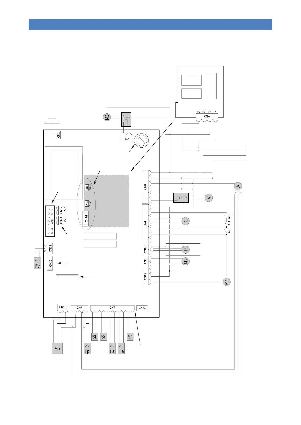
WIRING DIAGRAM
CONNECTOR FOR
BOOTLOADER
CONNECTION
PROGRAMMABLE TIMER-
CONTROLLED
THERMOSTAT CLOCK
BATTERY (TYPE CR2032 3
Volt)
Q055 EXPANSION
BOARD
CONNECTED TO
L023_8 WITH
CONNECTORS
CN10, CN12 AND
CN14
FOR THE ELECTRICAL CONNECTION TO THE
COUPLED BOILER, IT IS ADVISABLE TO
CONNECT A RELAY AT THE OUTPUT OF THE
DEDICATED WIRES BECAUSE THESE ARE
POWERED AT 230 V.
Q055 EXPANSION BOARD
(OPTIONAL)
COMPONENT LEGEND:
M1 = Screw feeder gearmotor
M2 = Turbulator cleaning gearmotor
M3 = Brazier cleaning gearmotor (configured
models only)
C = Ignition plug
A = Flue gas extractor with tachometer
P = Pump
V = Auxiliary pellet loading vacuum motor (optional
configuration)
SAFETY DEVICE KEY:
ALp = Fire door closure micro switch
ALf = Flue gas pressure switch
ALt = Manual reset thermostat
LEGEND FOR PROBES / CONTACTS / SENSORS
Sf = “Thermocouple type K” flue gas probe
Sc = Boiler H
2
O sensor “NTC type 10k ± 1%”
Sb = H
2
O integrated/external cylinder “NTC
type 10K ± 1%" (optional configuration)
Ta = Room thermostat contact
Fs = DHW flow switch (optional configuration)
Fp = Brazier cleaning micro-limit switch (configured
models only)
Sp = Pellet level sensor (mod. K048
Fv = Auxiliary vacuum loading closure micro switch
(optional preparation)
IMPORTANT: DO NOT
INVERT THE WIRES
CONFIGURATION
(WITH 230 V VOLTAGE)
FOR CONTROLLING A
COUPLED BOILER, IF
CONNECTED
CONFIGURATION FOR
CONNECTION OF THREE
-
WAY MOTOR
-DRIVEN
AUX2 AL3 N V2/P0 PBC N N AL1 AL2 CYL.
SC.F. EXCH. FLUE GAS N F
THREE-WAY CONNECTION LEGEND:
BLUE = Common
(Neutral 230 V)
BLACK = DHW side
(Live 230 V when DHW is requested)
BROWN = Heating side
(Live 230 V when DHW is not
requested)
YELLOW/GREEN = Earth
Cable for tachometer connection
AUXIN ENC +5V GND BLU PELLETS H2o AMB THERM +TC1- PMP PWM