Design and function Diaphragm Pumps N 143/186.12
12 Translation of original Operating and Installation Instructions, english, KNF 121610-121613 07/16
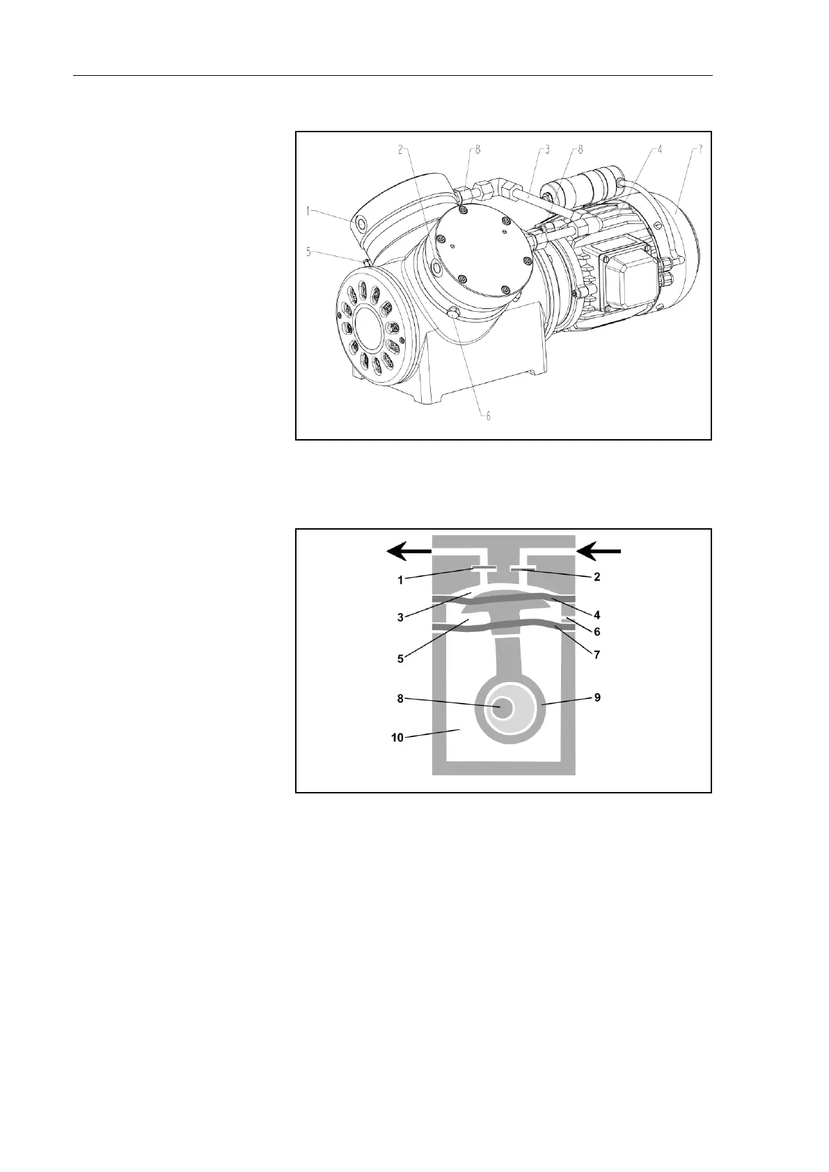
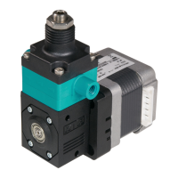
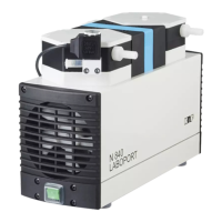
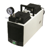
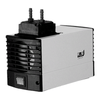
Design N 186.3_ _.12 E
1 Pneumatic outlet (G ¼)
2 Pneumatic inlet (G ¼)
3 Pneumatic head connection
4 Motor
5 Screw plug of hole for
pressure monitoring the di-
aphragm intermediate
space of head 2 (2x)
6 Screw plug of hole for
pressure monitoring the di-
aphragm intermediate
space of head 1 (2x)
7 Fan cover
8 Union nut
Fig. 3: Double diaphragm pump N 186.3 __.12 E
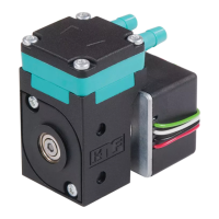
Function Double diaphragm pump
1 Outlet valve
2 Inlet valve
3 Transfer chamber
4 Working diaphragm
5 Innerspace
6 Hole for pressure monitor-
ing the innerspace (5)
7 Safety diaphragm
8 Eccentric
9 Connecting rod
10 Pump drive
Fig. 4: Pump head
Double diaphragm pumps transfer, compress (depending on pump
version) and evacuate gases and vapors.
The elastic working diaphragm (4) is moved up and down by the
eccentric (8) and the connecting rod (9). In the downward stroke it
aspirates the gas to be transferred via the inlet valve (2). In the
upward stroke, the working diaphragm presses the medium out of
the pump head via the outlet valve (1). The transfer chamber (3) is
hermetically separated from the pump drive (10) by the working
diaphragm and a safety diaphragm.
A second diaphragm (safety diaphragm (7)) is located underneath
the working diaphragm. This second diaphragm is under less