Diaphragm Pumps N 143/186.12 Design and function
Translation of original Operating and Installation Instructions, english, KNF 121610-121613 07/16 11
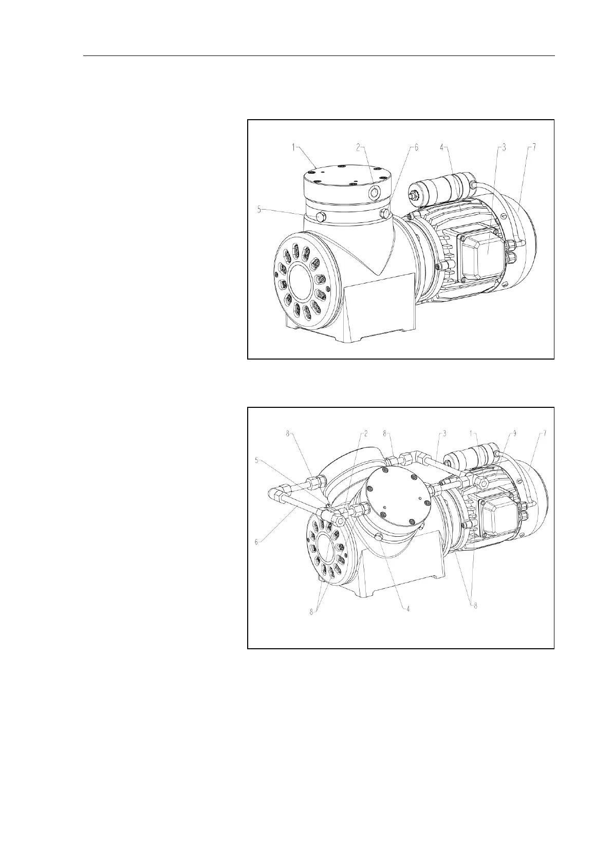
5. Design and function
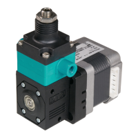
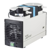
Design N 143 _ _.12 E
1 Pneumatic outlet (G ¼)
2 Pneumatic inlet (G ¼)
3 Terminal box (electrical
connection)
4 Motor
5,6 Screw plug of hole for
pressure monitoring the di-
aphragm intermediate
space
7 Fan cover
Fig. 1: Double diaphragm pump N 143 __.12 E
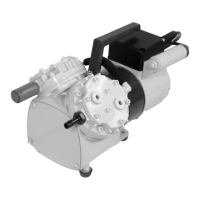
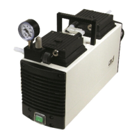
Design N 186.1.2_ _.12 E
1 Pneumatic inlet (Tube OD
10)
2 Pneumatic outlet (Tube OD
10)
3 Pneumatic head connection
suction side
4 Screw plug of hole for
pressure monitoring the di-
aphragm intermediate
space of head 1 (2x)
5 Screw plug of hole for
pressure monitoring the di-
aphragm intermediate
space of head 2 (2x)
6 Pneumatic head connection
pressure side
7 Fan cover
8 Union nut
9 Motor
Fig. 2: Double diaphragm pump N 186.1.2__.12 E