Installation and connection Diaphragm Pumps N 143/186.12
16 Translation of original Operating and Installation Instructions, english, KNF 121610-121613 07/16
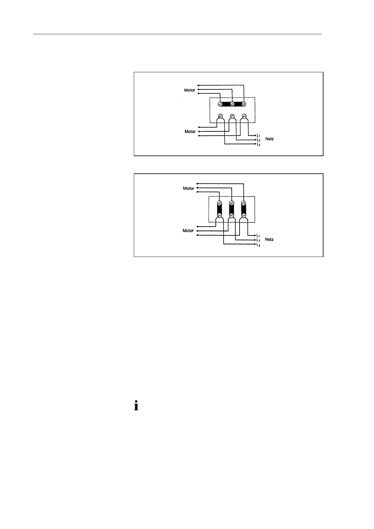
4. Connection of pumps with 3 phase motor according to figs. 7
or 8.
Fig. 7: Y-Connection (high voltage)
Fig. 8: ∆-Connection (low voltage)
5. Connect the earth (ground) wire to the motor.
6. Close the terminal cover box.
6.3. Pneumatic connection
Only connect components to the pump which are designed for
the pneumatic data of the pump (see chapter 4, Technical da-
ta).
Protect the compressors with a pressure relief device between
the pressure side of the compressor and the first shut-off valve.
If the pump is used as a vacuum pump, safely discharge the
pump exhaust at the pump’s pneumatic outlet.
Connecting pump
A marking on the pump head shows the direction of flow.
1. Remove the protective plugs from the hose connection
threads.
2. Connect the suction line and pressure line (see chapter 4,
table 9 for the mounting dimensions).
3. Lay the suction and pressure line at a downward angle to
prevent condensate from running into the pump.