9 FPGA connections
9.1 FPGA pins
The main FPGA signals are:
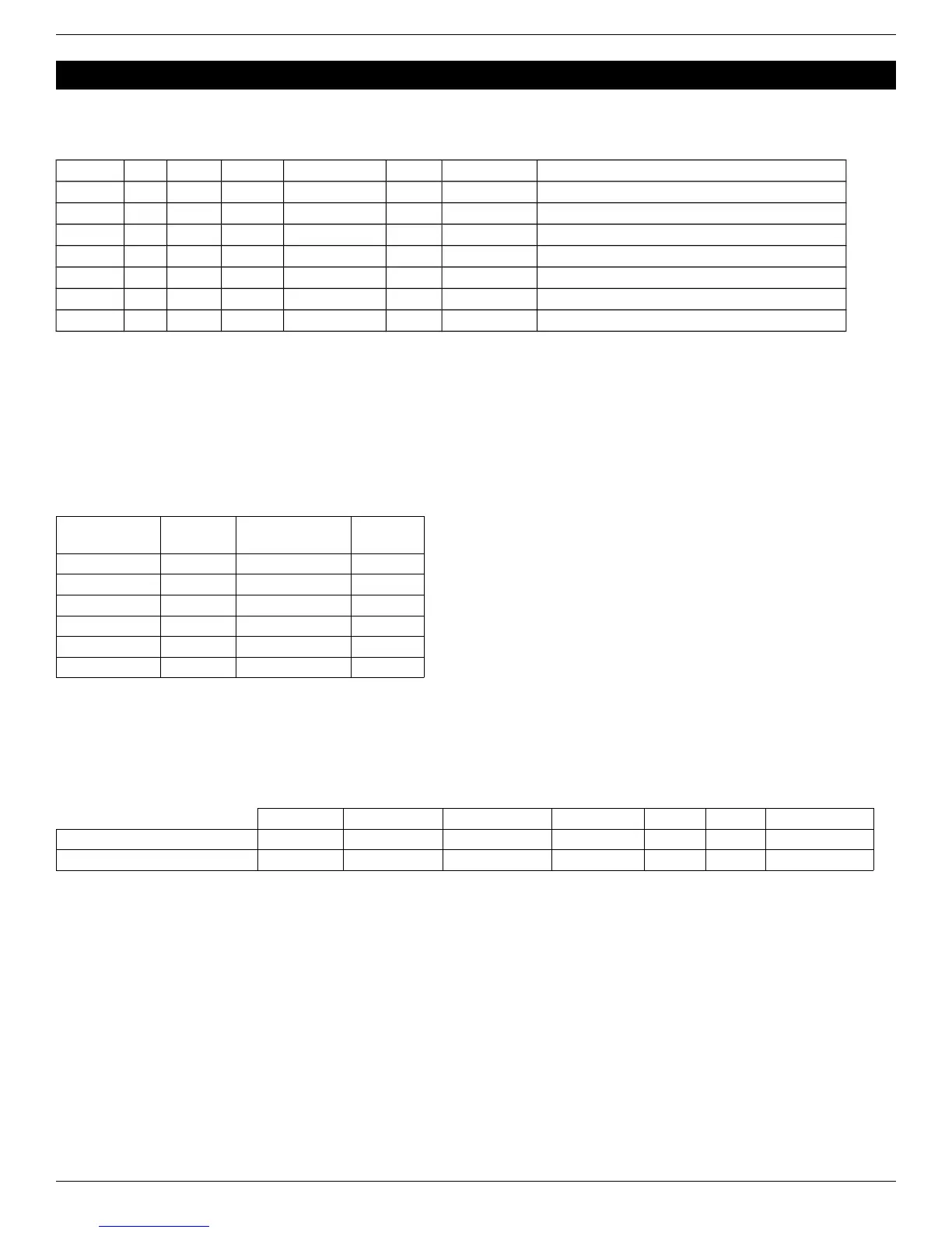
Pin name Pluto Pluto-II Pluto-IIx Pluto-IIx HDMI Pluto-3 Direction Comment
CLK0 91 10 40 40 17 FPGA input 25MHz on-board SMD oscillator, always present
CLK1 41 18 FPGA input Optional DIL8 oscillator (1)
LED1 7 25 29 29 28 FPGA output Red LED (active high)
LED2 28 25 FPGA output Red LED (active high)
PB 9 FPGA input Push-button (active low)
RxD 77 4 21 21 21 FPGA input FPGA receives from PC
TxD 78 29 30 30 24 FPGA output FPGA transmits to PC
(1) The optional oscillator is not present by default. It is to be added above the on-board SMD oscillator.
9.2 IO headers
Many IO signals are available on headers, see the drawings on chapter 18.
9.3 Boot-PROM connection (Pluto-II/-IIx/HDMI/-3)
The boot-PROM is an M25P10 or M25P40 or equivalent.
The pinout is as follow:
Boot-PROM
pin
Pluto-II
FPGA pin
Pluto-IIx / HDMI
FPGA pin
Pluto-3
FPGA pin
Clock 20 53 15
Data In 17 46 1
Data Out 5 51 14
CSn 6 27 2
HOLDn 40 31 8
Wn 89 N.A. N.A.
9.4 HDMI (Pluto-IIx/HDMI)
Each HDMI port uses 8 FPGA pins (4 differential pairs), plus some auxiliary lines (DDC I2C and “hot plug detect”).
● Pluto-IIx board: it doesn't have a native HDMI port but can be fitted with an optional HDMI adapter.
● Pluto-IIx HDMI board: it has a native HDMI port, and can also use an optional HDMI adapter, so in effect has two
possible HDMI outputs.
TMDS clock TMDS 0 (blue) TMDS 1 (green) TMDS 2 (red) I2C SDA I2C SCL Hot plug detect
Pluto-IIx HDMI (native output) 34 / 35 36 / 37 (1) 43 / 44 (1) 48 / 49 50 33 32
Pluto-IIx optional HDMI adapter 77 / 78 83 / 84 (1) 88 / 89 (1) 93 / 94 (2) (2) (2)
(1) Inverted TMDS lane – place an inverter in the FPGA. See the HDMI source code “TMDS_encoder” instantiations.
(2) If desired, the HDMI auxiliary lines can be wired manually to the FPGA.
9.5 Power header
This 3-pins header provides access to the power signals. It is often used as an output (to power other boards) but can
also be used as an input (to power the Pluto board).
On Pluto and Pluto-II, the power header pinout is:
1. VCC-unreg (board power, typically +5V to +10V)
2. GND
3. +3.3V (regulated by Pluto/Pluto-II)
On Pluto-IIx/HDMI and Pluto-3, the power header pinout is:
1. GND
2. +3.3V (regulated by Pluto-IIx/HDMI/-3)
3. VCC-unreg (board power, typically +5V to +10V)
FPGA RS-232 development boards Page 13