18
kobalttools.com
ASSEMBLY INSTRUCTIONS
kobalttools.com
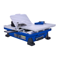
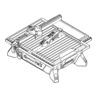
3. Slide locking level assembly (A) until the end of
rip guide rail (D) is ush with the machining area
on locking lever assembly. Rotate locking level
assembly knob clockwise to lock in place.
Note: The position of locking level assembly knob
can be adjusted by pulling out assembly knob,
rotating to desired position, then pushing back into
position.
4. Place front of rip guide rail (D) on front rail of tile
saw (R). Lower back of rip guide rail (D) to tile
saw (R).
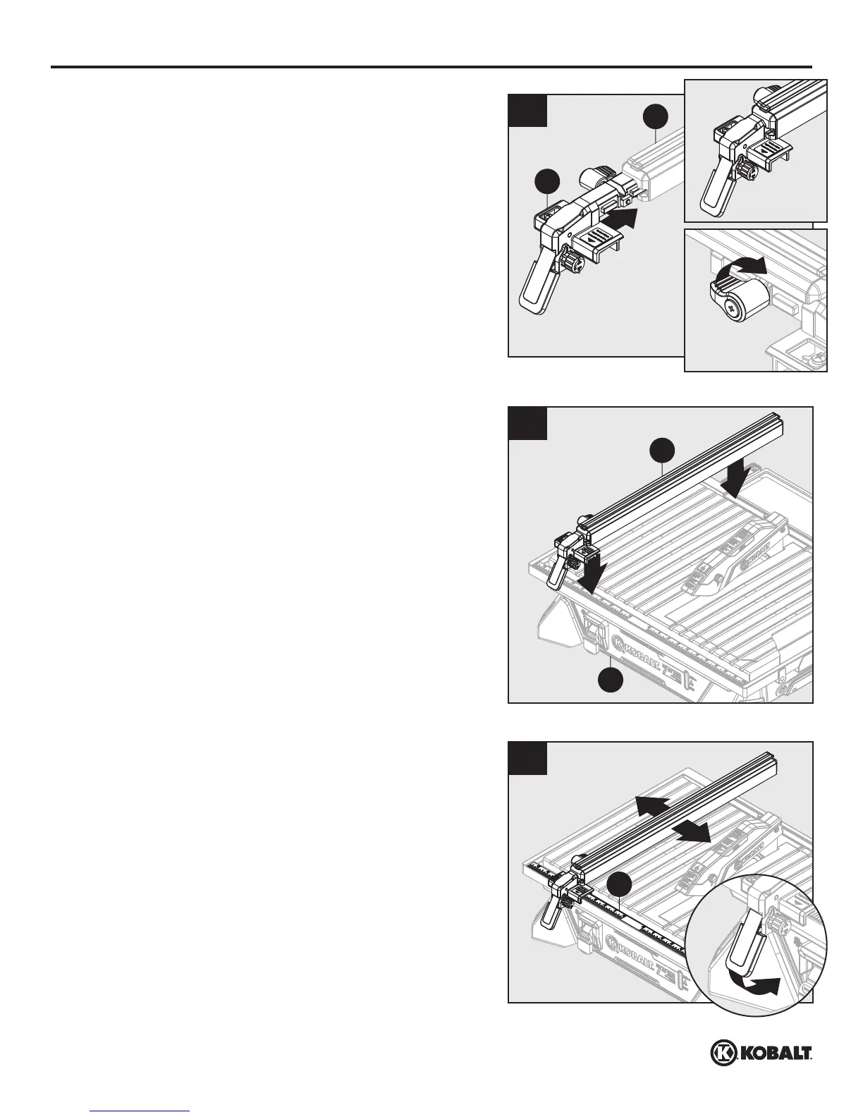
5. Use rip guide scale (P), located on front of table,
to set rip guide to desired width of cut. Push
locking lever down to secure to saw table.
Note: When securely locked, locking lever should
point downward.
1
1
3
D
A
4
D
R
1
1
5
P
 Loading...