20
$
Remove the shield cover located on the astern side. (There are four fixing screws.)
%
Remove the cable clamping plate and rubber ring, pass cable through the introduc-
tion opening, put the rubber ring from both ends of it, and clamp the cable to the
scanner unit with screws via the fixing plate. Connect 7-pin connector to X11 and
9-pin connector to X12 of PCB.
&
Replace the aluminum cover. At this time, attach a cable shield onto a ditch with
the aluminum cover. However, be careful that the cable will not be caught up be-
tween the main unit and cover.
'
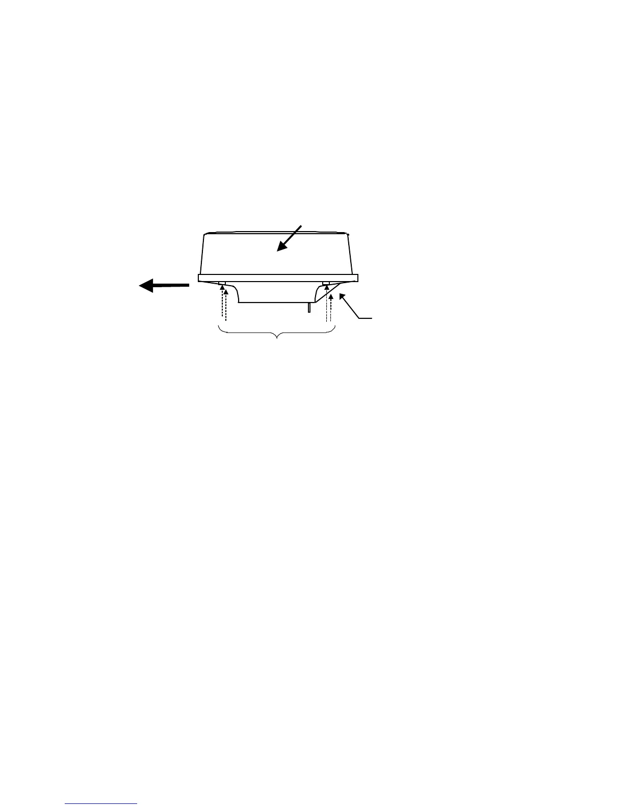
Replace the upper part of the radome. Be careful not to bump it against the an-
tenna in the same way as when removing it. Make sure that the cover is fitted in the
correct direction as shown in Fig.3-7-2. The upper and lower parts of the radome
each have four markings indicating screw positions. Align the upper and lower po-
sitions as you mount the radome.
Ship's
heading
Logo seal on
side wall
Fix four screws
Cable inlet
Fig.3-7-2 Fitting cover (RA41C)
 Loading...