SET UP SAFETY
10
10/11
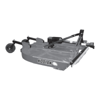
3-POINT LIFT TYPE SET UP
1. Loosen A-Frame and Lift Assembly to upright position.
2. Remove Bolt and Nut at top of A-Frame.
3. Back braces that were bolted to the outside of the upright arms should be moved to the inside of the upright arms
and loosely tightened to the top of A-Frame. Attach back braces to the cutter deck. Tighten all bolts.
4. Remove check plug from each gearbox, inspect for proper EP-0 Grease level. Gearbox lube cannot be accurately
checked until the unit has been operated for 15 - 20 minutes.
5. Install gearbox shield onto face of gearbox with the 4 bolts and washers provided in the face of the gearbox.
6. Grease both universal joints of the PTO shaft. Grease the telescoping surfaces of the PTO shaft.
Grease universal joints of coupling shafts between gearboxes.
7. Grease tailwheel forks.
8. Install gearbox end (slip clutch) of PTO shaft onto center gearbox.
9. If shearbolt unit, take retaining ring off gearbox shaft, slide PTO shaft on, install shearbolt and retaining clip
back on gearbox shaft. Failure to install the drive shaft retaining clip can result in damage to mower and drive
shaft, as well as injury or death.
PULL TYPE SET UP
1. Place cutter on 4” blocks.
2. Attach wheel lift tube to cutter deck.
3. Attach turn buckle to the deck and then to the wheel lift bracket. This controls wheel height of unit.
4. Attach tongue with 3/4” x 2 1/4” bolts to the front cutter ears.
5. Attach strap to the center front angle hole, and then to the tongue.
6. Tighten all bolts and nuts.
7. Remove check plug from gearbox, inspect for proper EP-0 Grease level. Gearbox lube cannot be accurately
checked until the unit has been operated for 15 - 20 minutes.
8. INSTALL Gearbox SHIELD ONTO FACE OF GEARBOX WITH THE 4 BOLTS AND WASHERS PROVIDED
ON THE FACE OF Gearbox.
9. Grease both universal joints of the PTO shart. Grease the telescoping surfaces of the PTO shaft.
Grease universal joints of coupling shafts between gearboxes.
10. Grease tailwheel forks and tubes.
11. Install gearbox end (slip clutch) of PTO shaft onto center gearbox.
12. If shearbolt unit, take retaining ring off gearbox shaft, slide PTO shaft on, install shearbolt and retaining clip
back on gearbox shaft. Failure to install the drive shaft retaining clip can result in damage to mower and drive
shaft, as well as injury or death.
13. BEFORE ENGAGING PTO, REMOVE BLOCKS FROM UNDER CUTTER.
WARNING
USE ONLY A 1/2” X 3” GRADE 2 SHEARBOLT AND LOCK WASHER. IF WRONG SIZE
OR GRADE SHEARBOLT IS USED, IT COULD RESULT IN THE FOLLOWING:
SERIOUS DAMAGE TO CUTTER AND/OR SERIOUS INJURY OR DEATH.
WARNING
FAILURE TO INSTALL RETAINING CLIP WILL ALLOW DRIVELINE TO SWING FREELY
IF BOLT IS SHEARED, CAUSING POSSIBLE INJURY OR DEATH.