KV3000 Kinematic Viscosity Bath
Operation and Instruction Manual
KV3000-Manual
-12-
3.3 Setup
Equipment Placement: Make sure the
instrument in placed on a firm, level table in an
area with adequate ventilation or in a hood. The
unit may be leveled by making minor turning
adjustments to the feet located at the base of
the unit. Please note that Koehler does not
supply a level with this equipment.
WARNING: Certain mechanical stresses
applied to the tempered glass front panel and
inner the inner borosilicate glass jar pose a
hazard to personnel. Impacts to these during
normal operation can shatter the glass
components releasing the bath fluid posing
thermal burn hazards and slipping hazards. For
this reason the instrument must be operated by
and accessible only to trained and authorized
personnel and located in an area where this type
of impact is likely to occur.
Environmental Conditions: The instrument
environment must comply with the following
conditions for proper setup:
No / Low Dust
No direct sunlight
Not near heating or AC ventilation ducts
No Vibrations
Clearance from other instruments
Temperature Range: 5 to 40°C
Elevation to 2000 meters
Relative Humidity: < 80%
Ventilation. A fume hood or exhaust system is
required when operating the unit. Flammable
vapors and/or steam are generated during
operation and must not be permitted to
accumulate. A canopy-style hood may be used if
the height from the top of the unit to the canopy
is 5 feet or less. The exhaust blower should
have a rating of 1000 C.F.M. or greater.
Power: Connect the line cords to properly fused
and grounded receptacles with the correct
voltage as indicated in section 1.3 or on the
back of the unit.
WARNING: For safety, disconnect the
power when performing any maintenance and/or
cleaning. Do NOT turn the power on unless the
bath is filled with the proper medium; otherwise,
damage may occur to the unit and the warranty
will be void.
4 Descriptions
4.1 Instrument Controls
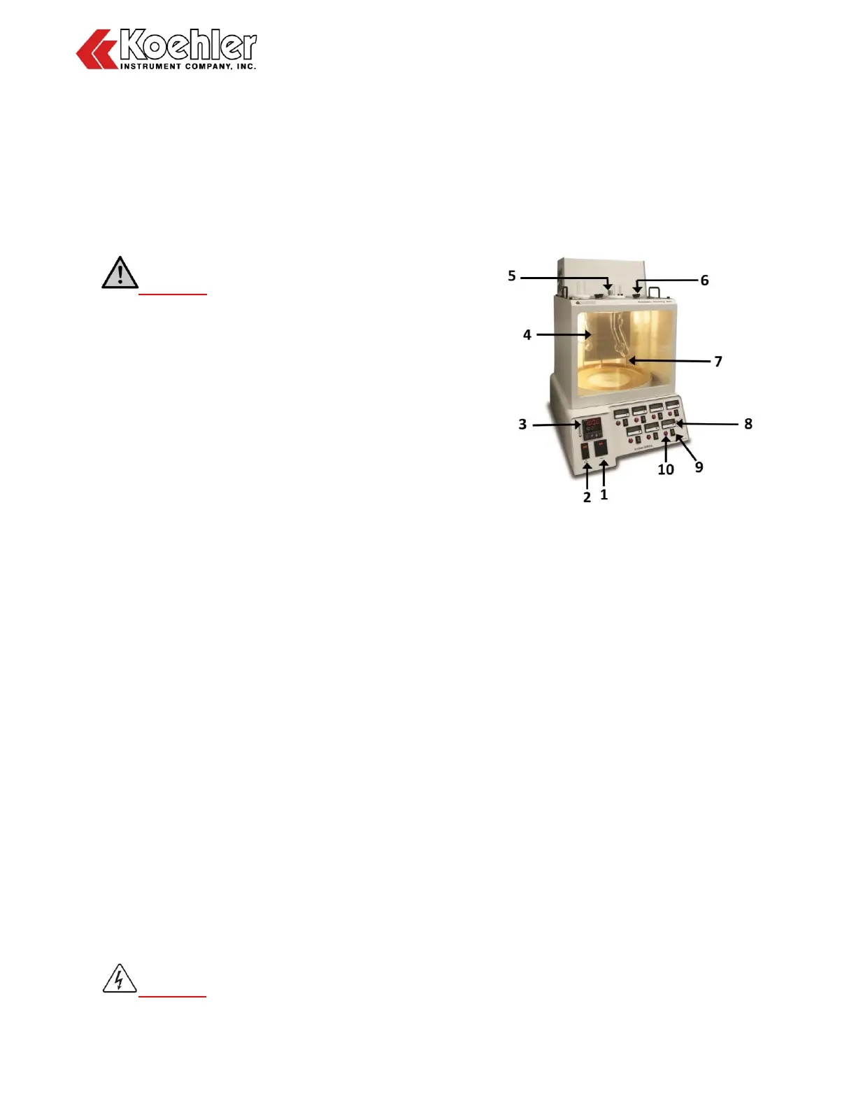
Figure 1: Instrument Descriptions
1. Power Switch. This switch controls the
power to the entire unit. When the
power switch is in the ON position, the
digital temperature controller, and the
stirrer are powered on.
2. Lamp Switch. This switch controls
turning ON/OFF the lamp for illuminating
the test samples.
3. Temperature Controller. The
temperature controller regulates the
bath temperature for the test procedure.
Refer to Section 4.3 for full operational
details.
4. Temperature Regulation: The heater
coils stabilize the bath temperature to
desired setting within ± 0.02°C. Running
coolant through the cooling coils allows
bath to maintain temperatures near or
below ambient.
5. Thermometer/Thermocouple Port:
This port allows for independent
temperature measurement of the bath
temperature with a thermometer or a Pt-
100 RTD probe for precise temperature
measurements and digital temperature