TP-6196 10/0950 Section 4 ADC 2100 and DC 2200 Controllers
Note: Some versions of the controller mount from
inside the controller compartment. Others are
front-mounted.
6. For inside-mounted controllers:
a. Remove 5 screws to remove the front panel on
the air intake end of the enclosure. Remove the
plastic caps to access the 2 side screws. See
Figure 4-17.
b. Remove two screws to remove the cover from
the controller compartment. See Figure 4-18.
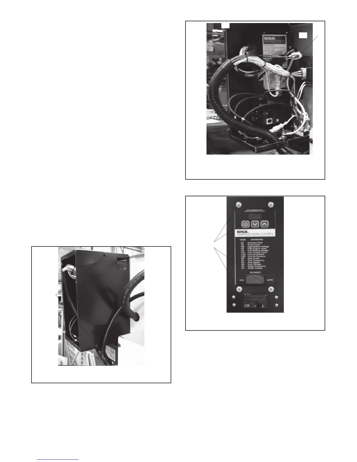
c. Disconnect wiring harness plugs P1, P15, and
P16 from the ADC controller. See Figure 4-19.
d. Loosen and remove four controller mounting
screws at the front of the controller. See
Figure 4-20. Remove the controller from the
compartment.
e. Place the new controller into position and install
the four mounting screws.
f. Attach connectors P1, P15, and P16 to the new
controller.
g. Replace the cover on the controller
compartment.
h. Replace the front panel on the air intake end of
the enclosure.
tp6196
1. Cover screws
1
Figure 4-18 Controller Compartment Cover
1
tp6196
1. P1 35-pin connector
2. P15 3-pin connector
3. P16 6-pin connector
2
3
Figure 4-19 Controller Connections
1
tp6196
1. Controller mounting screws (4 ea.)
Figure 4-20 Controller Mounting Screws
(inside-mounted controller shown)

 Loading...


