TP-6196 10/09 89Section 6 Component Testing and Adjustment
6.10 Mechanical Governor
Mechanical governors are used on model 12RESL,
12RESM1, and 12RESNT generator sets. See
Figure 6-25. This section includes governor adjustment
procedures. See the engine service manual for a
description of mechanical governor design and
operation, if desired.
1
photo4991
1. Mechanical governor assembly
Figure 6-25 Mechanical Governor Assembly Location
Mechanical Governor Arm Adjustment Procedure
Make this adjustment whenever the governor arm is
loosened or removed from the cross shaft. See
Figure 6-26 and adjust as follows:
1. Make sure the throttle linkage is connected to the
governor arm and the throttle lever on the
carburetor.
2. Loosen the hex nut holding the governor lever to
the cross shaft.
3. Move the governor lever toward the carburetor as
far as it will move (wide open throttle) and hold in
this position.
4. Insert a nail into the hole in the cross shaft and
rotate the shaft counterclockwise as far as it will
turn. Tighten the hex nut securely and then remove
the nail.
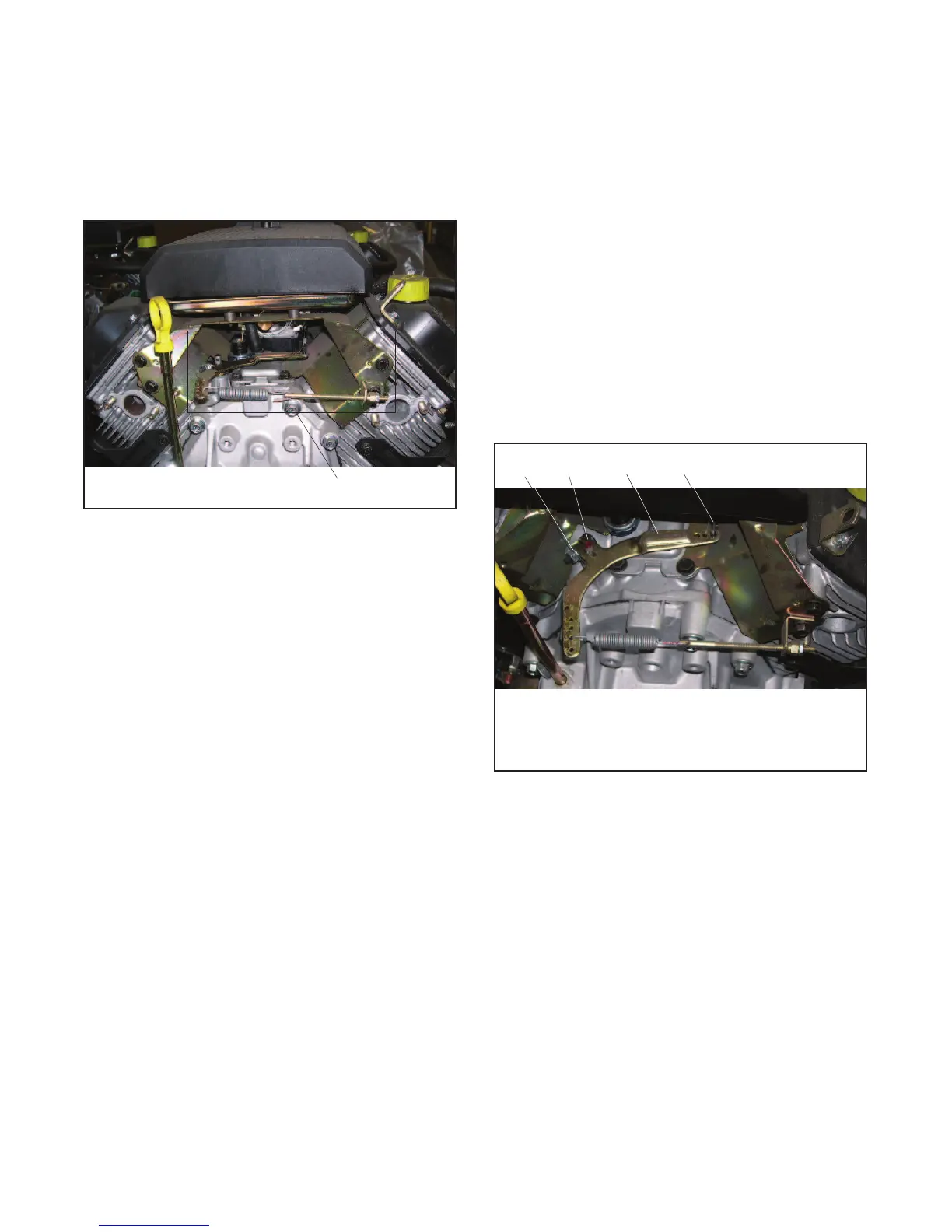
1. Hex nut
2. Cross shaft
3. Governor lever
4. Throttle linkage (passes under air cleaner)
1 2 3 4
photo5005
Figure 6-26 Governor Arm Adjustment
 Loading...


