TP-6196 10/0990 Section 6 Component Testing and Adjustment
Mechanical Governor Sensitivity Adjustment
Note: Often hunting/surging problems thought to be
caused by the governor are actually caused by
engine or carburetor problems. If the generator
set speed is unstable, hunts, or surges, check for
the cause using the procedure in Section 6.9.3
before proceeding.
Governor sensitivity is adjusted by repositioning the
governor spring in the holes of the governor lever. If
speed surging occurs with a change in engine load,
decrease the governor sensitivity. If a drop in speed
occurs when normal load is applied, increase the
governor sensitivity. See Figure 6-27 and adjust as
follows:
1. To increase the sensitivity, move the spring closer
to the governor cross shaft.
2. To decrease the sensitivity, move the spring away
from the governor cross shaft.
#
1. Governor lever
2. Cross shaft
1
2
photo5005
Figure 6-27 Governor Sensitivity Adjustment
Engine Speed (Frequency) Adjustment,
Mechanical Governor
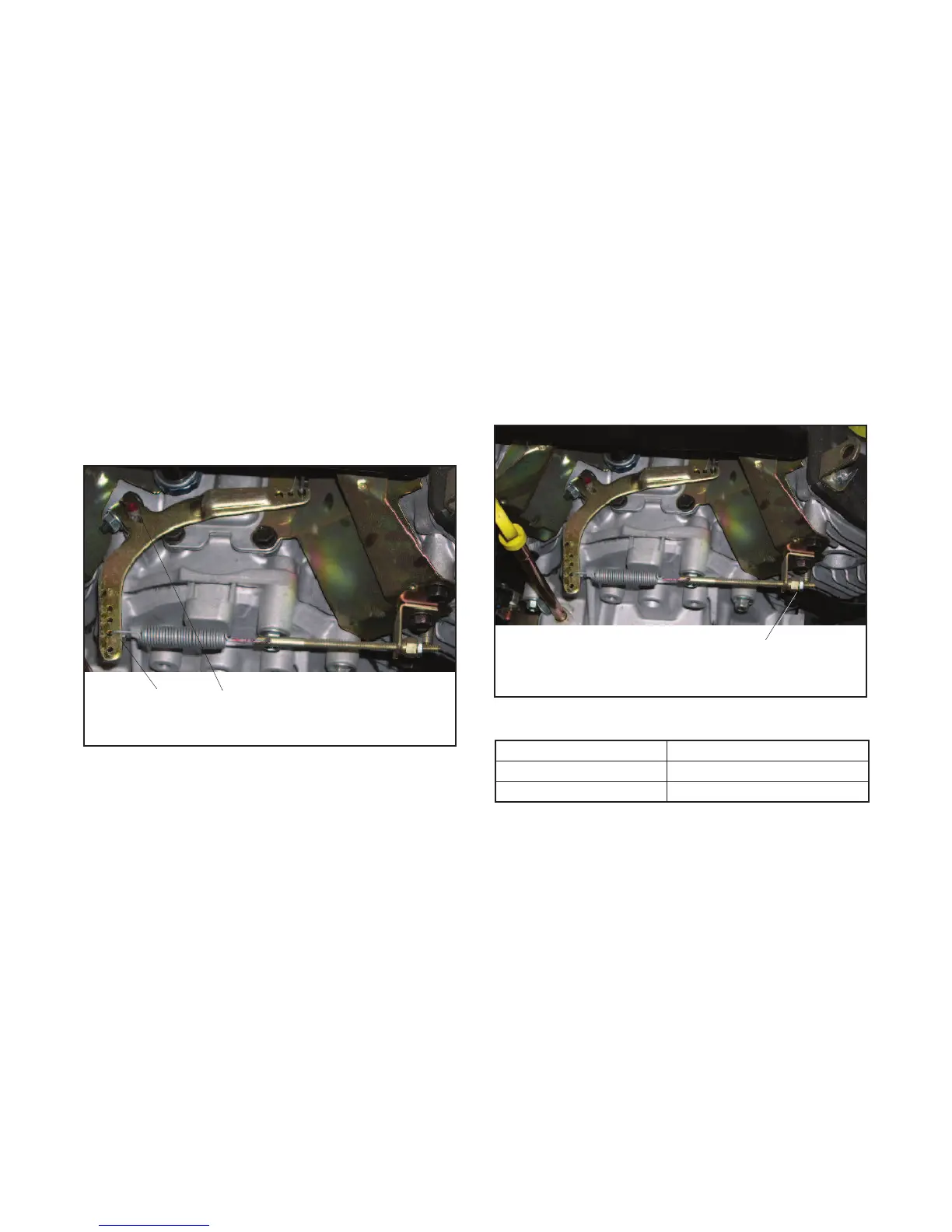
Use the adjusting nut shown in Figure 6-28 to adjust the
engine speed, if necessary. Recommended engine
speeds with no load and full load are shown in
Figure 6-29.
1. With the engine running, loosen the lock nut.
2. If the engine is running too slow (frequency is low),
turn the adjusting nut clockwise to increase the
speed.
3. If the engine is running too fast, turn the adjusting
nut counterclockwise, backing the nut out and
decreasing the speed.
4. Verify that the engine speed is correct and tighten
the locknut.
1
photo5005
1. Speed adjusting nut and lock nut
Figure 6-28 Engine Speed Adjustment
Generator Set Load Engine Speed
No Load 3780 RPM (63 Hz)
Full Load 3600 RPM (60 Hz)
Figure 6-29 Recommended Engine Speed

 Loading...


