TP-6984 5/17a 13Section 1 Installation
1. Specification
Number
1
8RESV-SA1
GM88347-GA7
XXXXXXXX
XXXXXXXX
29
1
3600
12V
NAT GAS
STANDBY
240
2F3
H
07/31/2015
7.00
7.00
1.0
60
Service Duty
Voltage
Alt Model
Insulation
MFG Date
Amps
Phase
RPM
Battery
Fuel
kW
kVA
Hz
Genset Model
Spec Number
Serial Number
Material Number
PF
Figure 1-2 Name Plate
1.4.1 Mounting Area
The generator set is shipped on a wooden pallet.
Remove the wooden pallet before positioning the
generator set. Prepare a flat, level mounting area
covered with a weed barrier and gravel or a concrete
mounting pad. Set the generator set directly on the
gravel or concrete.
Note: When installing a concrete mounting pad, the
generator set must be secured to the mounting
pad to prevent shifting or movement caused by
engine vibration. For mounting pads
GM92228-KP1-QS and GM92228-KP2-QS, use
the screw inserts in the mounting pad to secure
the generator set. See TT--1619 for concrete
mounting pad installation instructions.
Do not install the generator set directly on grass, wood,
or other combustible materials. Clear all combustible
materials, including plants and shrubs, building
materials, and lawn furniture, from an area at least 1.2 m
(4 ft.) beyond the exhaust end of the generator set. See
the dimension drawing in Section 3.
1.4.2 Exhaust Requirements
Hot engine and exhaust system.
Can cause severe injury or death.
Do not work on the generator set until
it cools.
WARNING
Servicing the exhaust system. Hot parts can cause
severe injury or death. Do not touch hot engine parts. The
engine and exhaust system components become extremely
hot during operation.
Figure 1 -3 gives the exhaust temperature at rated load.
Mount the generator set so that the hot exhaust does not
blow on plants or other combustible materials. Maintain
the clearances shown in the dimension drawing in
Section 3.
Exhaust Model
Temperature,
_C(_F)
Exhaust gas exiting the
enclosure at rated kW,
_C(_F)
8RESV(L) 190 (374)
10/12RESV(L) 106 (224)
Figure 1-3 Exhaust Flow and Temperature
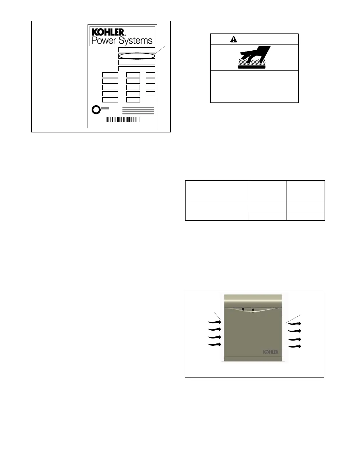
The generator set requires correct air flow for cooling
and combustion. The inlet and outlet openings in the
sound enclosure provide the cooling and combustion
air. Figure 1-4 shows the locations of the cooling a ir
intake and exhaust vents. Inspect the air inlet and outlet
openings inside and outside the housing to ensure that
the air flow is not blocked.
tp6879
1. Air intake
2. Exhaust outlet
1
2
FRONT VIEW
Figure 1-4 Cooling Air Intake and Exhaust

 Loading...


