EasyManuals Logo

Kohler 25CCL User Manual

Kohler 25CCL
176 pages
To Next Page IconTo Next Page
To Previous Page IconTo Previous Page
Page #138 background imageLoading...
Page #138 background image
138 TP-6694 6/22
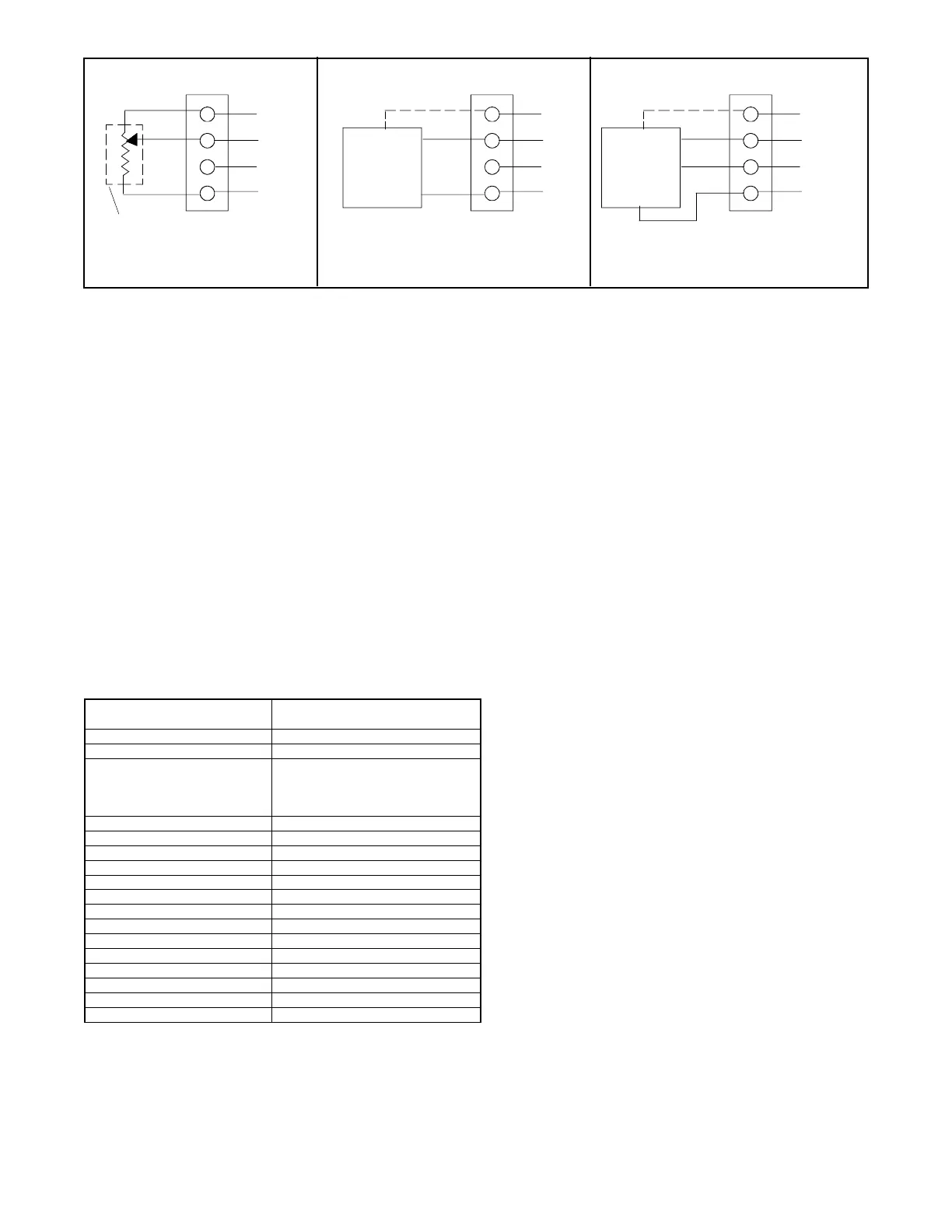
Figure 68 Dry Contact Kit Analog Input Connections P36
Program the inputs and outputs using SiteTech
Use a computer with Kohler SiteTech™ software to assign functions to digital and analog inputs and outputs. Each input and
output corresponds to a controller connection. Verify that the settings are appropriate for the connected sensor, switch, or
equipment. Do not change factory-set inputs and outputs without verifying the input and output connections.
Refer to Introduction-List of Related Materials for the SiteTech™ Software Operation Manual part no.
SiteTech™ input and output parameters C1 through C14 are designated for use on the four input/fifteen output module. See
Figure 69.
Test Dry Contact Relays
Verify the dry contact relay function by using the following procedure when troubleshooting.
1. Remove the user-supplied device wiring from the relay dry contact terminals.
2. Test the relay operation by connecting an ohmmeter across the NO and C terminals on the relay terminal strip.
3. Use a jumper wire to ground the selected fault terminal on the controller connection terminal strip. The relay contacts
should close and the ohmmeter should display a low resistance reading (continuity).
4. Install the user-supplied device wiring on the relay dry contact output terminals
SiteTech I/O Name
Optional Dry Contact Board
Connection
Analog Input C1
P36 Analog Input VN1/VP1
Analog Input C2
P36 Analog Input VN2/VP2
Digital Input C1
Digital Input C2
Digital Input C3
Digital Input C4
TB6 DI1
TB6 DI2
TB6 DI3
TB6 DI4
Digital Output C1
TB7 K1
Digital Output C2
TB7 K2
Digital Output C3
TB8 K3
Digital Output C4
TB8 K4
Digital Output C5
TB9 K5
Digital Output C6
TB9 K6
Digital Output C7
TB10 K7
Digital Output C8
TB10 K8
Digital Output C9
TB11 K9
Digital Output C10
TB11 K10
Digital Output C11
TB12 K11
Digital Output C12
TB12 K12
Digital Output C13
TB13 K13
Digital Output C14
TB13 K14
Figure 69 Optional Inputs and Outputs with 4 Input/15 Output Module
Optional 5 V Power
(50 mA max.)
Optional 5 V Power
(50 mA max.)
100 ohm min. or
50 mA max. current
0-5 Volt Ratiometric Sensor
0-5 Volt Analog Device
+/- 3 Volt Analog Device
TP-6694-6
P36
+5
VPx
VNx
GND
+5
VPx
VNx
GND
+5
VPx
VNx
GND
P36
P36
Analog
Device
Output
GND
GND
Analog
Device
+
-

Table of Contents

Questions and Answers:

Question and Answer IconNeed help?

Do you have a question about the Kohler 25CCL and is the answer not in the manual?

Kohler 25CCL Specifications

General IconGeneral
BrandKohler
Model25CCL
CategoryPortable Generator
LanguageEnglish

Related product manuals