TP-6081 4/004 Section 2 Operation
2.4.1 Controls and Indicators
The following table describes the controls and indicators
located at the controller:
Name Description
Start/Stop Switch Use this switch to start and stop the
generator set. Press the switch to
theSTARTpositiontostartthe
generator set. Press the switch to
theSTOPpositiontostopthe
generator set.
AC Circuit Breaker The circuit breaker trips on
overcurrent. During maintenance of
the vehicle wiring, the circuit breaker
disconnects the generator set.
Place the circuit breaker in the ON
position to close the circuit breaker.
Input Fuse This fuse protects the controller
circuitry.
Battery Charging
Fuse
This fuse protects the battery
charging circuitry.
Voltage Regulator
Fuse
This fuse protects the voltage
regulator circuitry.
Remote Start
Connector
A 6-pin connector on the controller’s
back panel allows connection of the
(optional) remote start kits
.
Hourmeter This meter records the total
generator set operating hours for
reference in maintenance
scheduling.
2.4.2 Starting the Generator Set
Hold the generator set controller start/stop switch or the
remote start/stop switch in the START position until the
unit starts.
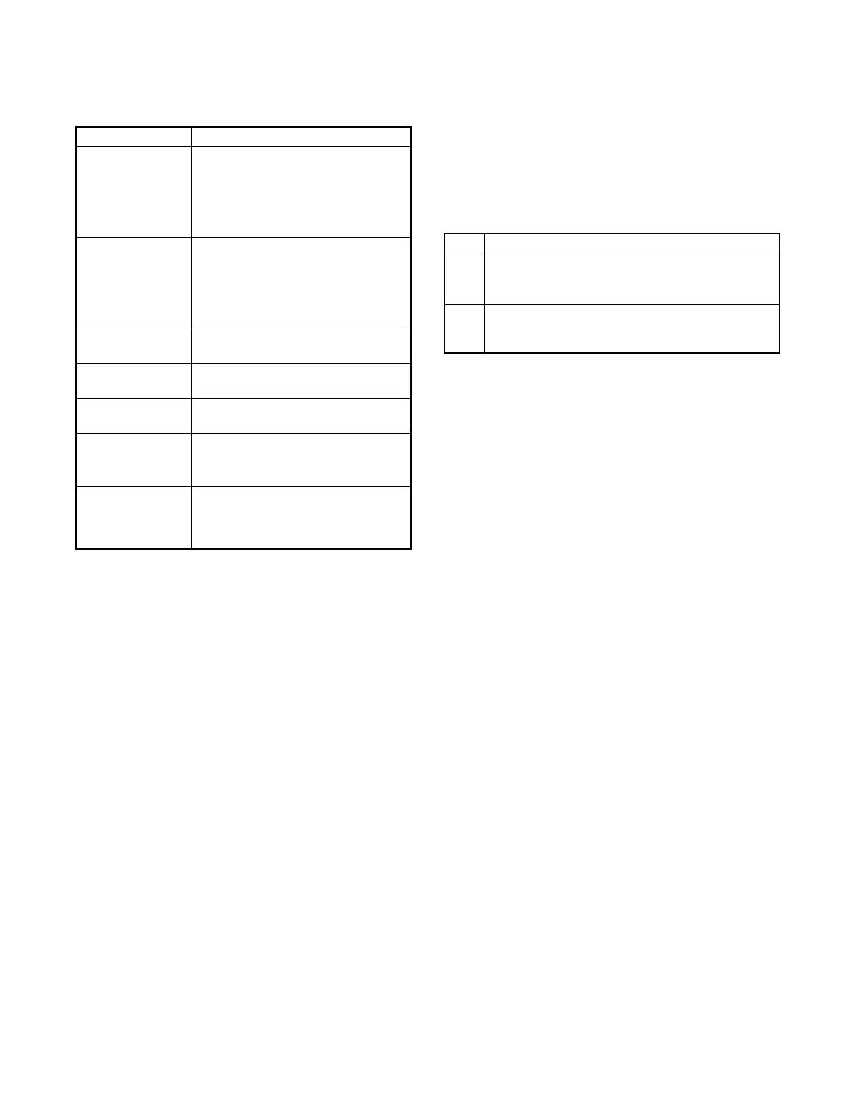
2.4.3 Stopping the Generator Set
The following table describes the actions required to
stop the generator set:
Step
ction
1 Cooldown
Run the generator set at no load for 5 minutes to
ensure adequate engine cooldown.
2 Stopping
Place the controller start/stop switch or remote
start/stop switch in the STOP position.
 Loading...