TP-6842 7/15 Section 1 Installation 17
1.8.4 Power Supply
Provide AC power for the battery charger (integral to
the VSC controller) and optional carburetor heater.
The power requirements are shown in Figure 1-10.
The power source must be GFCI protected. The
power to the accessories must be available at all
times, i.e. the circuit must be powered by the primary
source and backed up by the generator.
Be sure to disconnect power at the distribution panel
before making the connections. Connect power leads
to the utility power connection points on the terminal
block shown in Figure 1-9. See Section 1.8.3 and the
wiring diagrams in Section 2 for connection details.
Figure 1-10
Figure 1-10 Power Requirements
1.8.5 Programmable Interface Module
(PIM) Connection
One programmable interface module can be
connected to the generator set. Route low-voltage
communication leads through separate conduit. All
connections must comply with applicable state and
local codes.
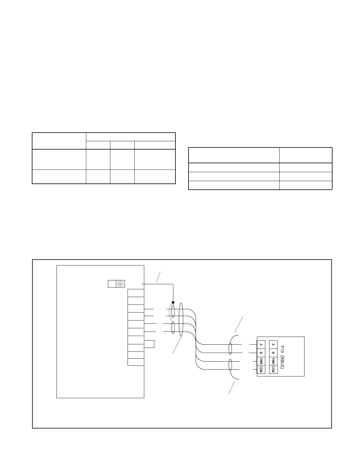
See Figure 1-12. Use Belden #9402 or equivalent
20 AWG shielded, twisted-pair cable to connect P10-1
through P10-4 on the programmable interface module
(PIM) to the generator set terminal block TB1
connections A, B, PWR, and COM. Note the shield
connections shown in Figure 1-12. The maximum
cable length using Belden #9402 cable is 61 m
(200 ft.).
For longer cable runs, use Belden #8762 or equivalent
20 AWG shielded, twisted-pair cable with 2 conductors
for the A and B connections, and use 12-14 AWG wire
for the COM and PWR connections. See Figure 1-11
for the maximum cable lengths.
Figure 1-11
Figure 1-11 Maximum Cable Lengths
Figure 1-12
Figure 1-12 Programmable Interface Module (PIM) Communication Connection to Generator Set Terminal Block
Equipment
Power Requirement, Max.
Watts Amps Volts
Battery charger
(standard, integral to
VSC controller)
120 1 100-250 VAC
50/60 Hz
Carburetor heater
(optional)
37 0.33 120 VAC
50/60 Hz
Cable
PWR and COM Connections
Maximum length
meters (ft.)
Belden #9402 or equivalent 20AWG 61 (200)
14 AWG 152 (500)
12 AWG 152 (500)
Programmable Interface
Module (PIM)
Generator Set
COM
PWR
B
A
PIM
COM
PWR
B
A
2
GND
A
B
COM
PWR
3
4
TB2
RBUS
12 VDC
1
1A
OPEN
OPEN
1
3
3
KPS_067
1. Connect one end of each cable shield to GROUND at the generator set.
2. Communication cable Belden #9402 or equivalent 20 AWG shielded, twisted-pair cable
3. Leave one end of each cable shield disconnected.
Note: Check the decal on the generator set for terminal block connections.

 Loading...


