22 Section 1 Installation TP-6842 7/15
Figure 1-20
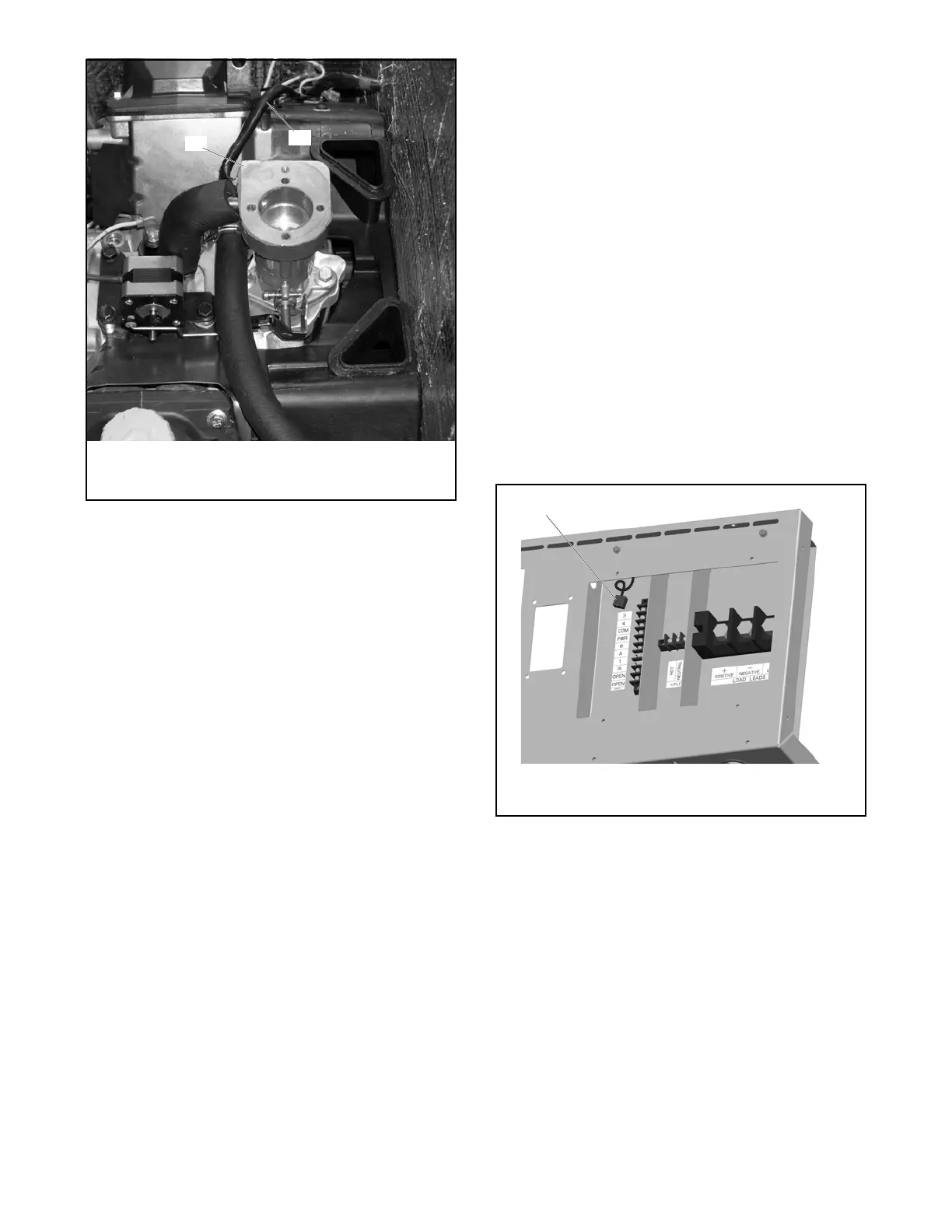
Figure 1-20 6VSG Carburetor Heater
1.10.2 OnCue
®
Generator Management
System
The OnCue
®
Generator Management System allows
monitoring and control of your generator set from a
personal computer located in your home or at other
remote locations. OnCue
®
can also be configured to
send email or text message notifications in the event
of a generator set fault. See TP-6796, OnCue
®
Software Operation Manual, for software instructions.
The OnCue
®
system is available separately as a loose
kit. Use category 5E network cable to connect the
VSC controller to the customer-supplied Ethernet
router and cable or DSL modem. Route the cable with
other low-voltage signal wiring (for example, the RBUS
communication leads or engine start leads), in
separate conduit from the AC accessory power. If the
network cable is longer than 100 meters (328 ft.), use
a repeater or switch.
Recommended: Use a laptop computer to verify the
network connection before connecting to the generator
set.
Checking the network connection
1. Check for and turn off any wireless connections
to the laptop.
2. Connect the network cable to the laptop. Connect
the other end of the network cable to the
customer’s router or modem.
3. Verify the Internet connection by opening your
web browser and going to www.kohlerpower.com
or another website.
4. After verifying the connection through the
network cable, disconnect the network cable from
the laptop and turn the laptop wireless
connections back on.
Connect to the Ethernet cable in the customer
connection area of the generator set. See
Figure 1-21. Use an RJ-45 inline coupler, provided
with the OnCue
®
kit, to connect the customer’s
Ethernet cable to the cable in the customer connection
box.
Figure 1-21
Figure 1-21 Network Connection for OnCue
®
1.10.3 Communications Kit
The optional communications kit is factory installed.
The communications kit includes the following items:
• Interface board with factory set inputs and outputs
• Customer connection terminal blocks
• Enclosure intrusion alarm switch
• Fuel pressure sensor
Connect the outputs to customer-supplied equipment
as shown in Section 1.8.7, Communications Kit Output
Connections, or on the wiring diagram.
Figure 1-22
1. Carburetor heater (air cleaner removed to show heater)
2. Carburetor heater power cord
1. Ethernet cable for optional OnCue
®
connection

 Loading...


