18 Section 1 Installation TP-6842 7/15
1.8.6 PIM Input and Output Connections
The optional programmable interface module (PIM)
provides two programmable inputs and six dry contact
outputs, four of which are programmable. See
TT-1584 for PIM installation and connection
instructions.
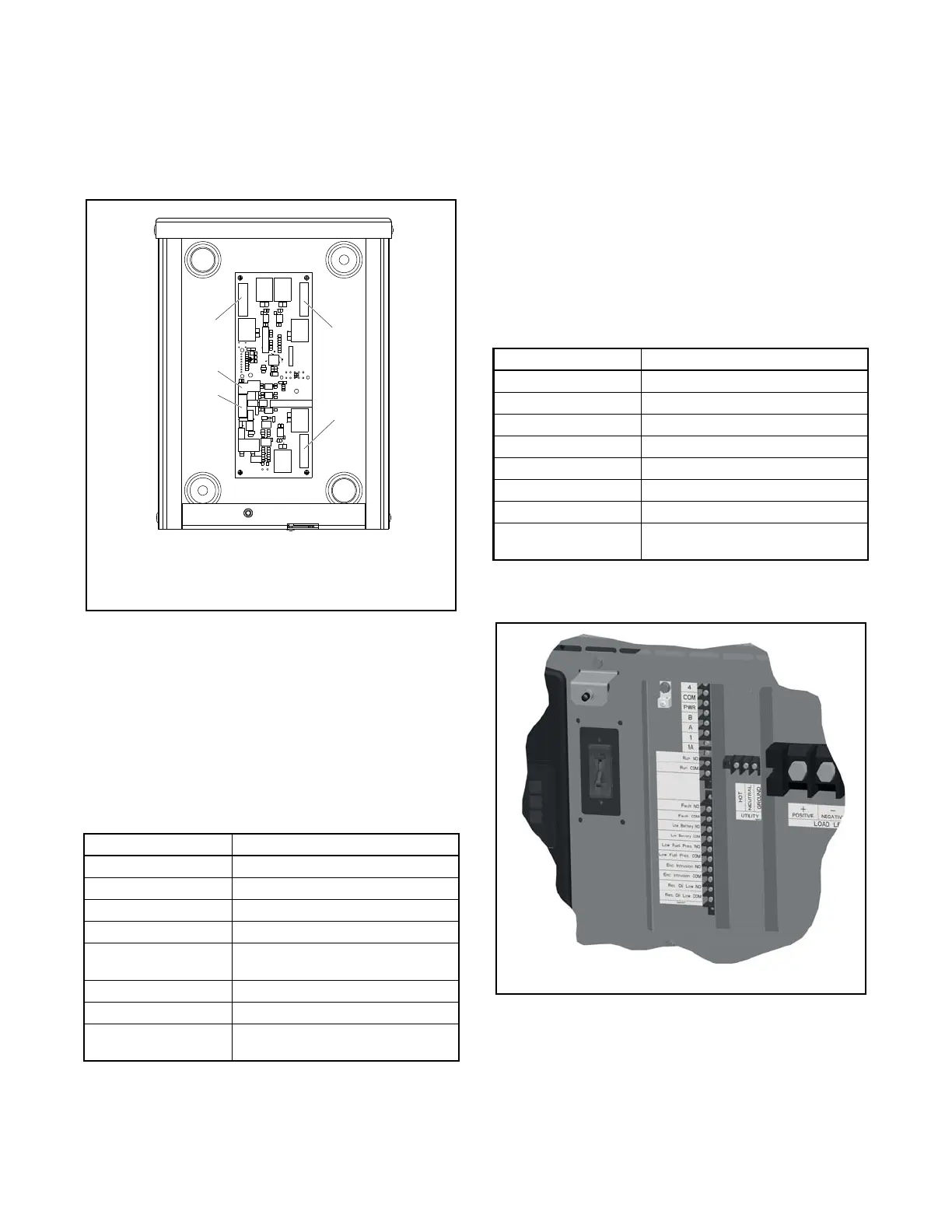
Figure 1-13
Figure 1-13 Optional PIM
The default settings for the inputs and outputs are
shown in Figure 1-14. To change the input and output
settings, use a personal computer running Kohler
®
SiteTech
™
software. See TP-6701, SiteTech Software
Operation Manual, for instructions.
A personal computer running Kohler OnCue
®
software
can be used to actively control PIM outputs. See the
OnCue
®
Software Operation Manual for instructions.
Figure 1-14
Figure 1-14 PIM Factory Default Inputs and Outputs
1.8.7 Communications Kit Output
Connections
The communications kit includes an interface board,
which is factory-installed inside the generator set
enclosure. The inputs and outputs are factory-set to
the settings shown in Figure 1-15.
The outputs are factory-wired from the circuit board to
terminal blocks in the customer connection area. Do
not attempt to connect directly to the interface board.
The output contacts are normally open (NO); outputs
close on activation. Connect customer equipment to
the outputs at the terminal blocks as shown in
Figure 1-15.
Figure 1-15
Figure 1-15 Communications Kit Factory Default
Inputs and Outputs
Figure 1-16
Figure 1-16 Communications Kit Output Connections
Connection PIM Settings
Input 1 None
Input 2 None
Output 1 (Relay 1) Run
Output 2 (Relay 2) Common Fault
Output 3 (Relay 3) Low Battery Voltage
(Programmable)
Output 4 (Relay 4) Not in Auto (Programmable)
Output 5 (Relay 5) Cooldown (Programmable)
Output 6 (Relay 6) Normal Source Failure
(Programmable)
1. Output connections (3 terminal blocks, 6 outputs)
2. Input connections (2 inputs)
3. Rbus communication connection to generator set terminal
Connection Communications Kit
Input 1 Fuel Pressure
Input 2 Enclosure Intrusion Alarm
Output 1 (Relay 1) Run
Output 2 (Relay 2) Common Fault
Output 3 (Relay 3) Battery Voltage
Output 4 (Relay 4) Fuel Pressure Low Warning
Output 5 (Relay 5) Enclosure Intrusion Alarm Warning
Output 6 (Relay 6) Reserve Oil Empty (oil makeup kit
required)
1. Output connections (6 outputs)

 Loading...


