Electrical System
5532 690 03 Rev. I KohlerEngines.com
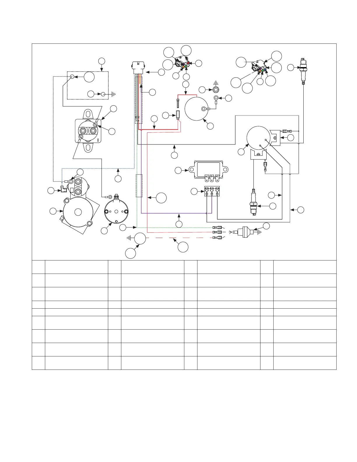
Wiring Diagram-Electronic Ignition System with Smart-Choke
™
System*
H
Q
L
G
AD
D
D
S
T
H
M
K
F
D
J
I
G
E
C
B
A
U
V
W
X
Y
Z
S
R
P
Q
Q
N
O
AA
AB
AE
AF
AF
AC
AB
AC
AG
AH
AJ
AI
A Starter Solenoid Tang B
Solenoid Shift
Starter Assembly
C
Inertia Driver
Starter Assembly
D Green
E Violet (Charging) F Oil Sentry
TM
(Optional) G Spark Plug(s) H
White
(AC Charging Leads)
I
Rectifi er-Regulator
Connector
J Rectifi er-Regulator K
Flywheel Stator
Assembly
L Ignition Module(s)
M Intake Manifold Screw N Ground O Carburetor P White (Ignition Kill)
Q Red R Solenoid Lead S Orange T Connector
U Blue V Starter Solenoid Stud W Relay Stud X
Relay Cranking
(Customer Supplied)
Y Battery Negative Z Battery AA Battery Positive AB
Violet (shown)
or Orange
AC White AD
Orange (shown)
or Red
AE Blue (shown) or Red AF Polarity Rib
AG
Solenoid Shift Starter
Assembly (Optional)
AH Thermostat Assembly AI Red AJ Red w/Black Line
*For engines with eChoke
™
, refer to component illustrations in Fuel Section of this manual.
 Loading...