Do you have a question about the Kohler KDW 702 and is the answer not in the manual?
Details concerning the engine's approval references and directives.
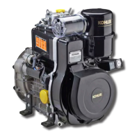
Explains the information found on the engine's identification plate.
Describes the nameplate for EPA rules applied on the rocker-arm cap.
Provides an example of how to interpret the engine's compilation data.
Lists essential safety rules and precautions for operating the engine.
Details the emission control system warranty for engines sold in California.
Outlines the owner's obligations for maintaining warranty coverage.
Specifies the duration and scope of the engine's warranty coverage.
Explains the meaning of various safety pictograms found on the engine or manual.
Shows the locations on the engine where safety pictograms are placed.
Provides comprehensive details of the 3-year limited warranty for Kohler diesel engines.
Offers important notes and guidelines for using the service manual.
Defines key terms and jargon used throughout the manual.
Provides a guide to identify and resolve common engine anomalies and symptoms.
Lists detailed technical data, dimensions, and performance parameters of the engines.
Presents graphical representations of engine power, torque, and fuel consumption.
Shows dimensional drawings and measurements for different engine models.
Outlines the basic maintenance tasks to be performed regularly.
Covers routine checks and replacements at specified intervals.
Details maintenance operations required at longer intervals or for specific issues.
Explains lubricant classifications (API, ACEA, MIL) and SAE grades.
Describes how SAE grades define oil viscosity based on temperature.
Covers global standards for lubricant testing and qualification.
Details the European Automobile Manufacturers Association (ACEA) sequences for lubricants.
Explains American Petroleum Institute (API) and military (MIL) lubricant specifications.
Specifies the recommended lubricant type and brand for the engine.
Lists the oil volume required for different engine models and oil sump types.
Information regarding coolant types, mixtures, and safety precautions.
Guidelines for selecting and using appropriate diesel fuel types.
Recommendations for using winter fuels to prevent paraffin formation.
Advises on the suitability and limitations of using biodiesel fuels.
Lists aviation fuels that can be used in the engine.
Notes regarding emission labels and fuel requirements for compliance.
General guidelines and precautions before starting disassembly and assembly operations.
Specific advice for carrying out engine overhauls and tuning procedures.
Details on the disassembly, cleaning, and specifications of the dry air filter.
Explains the function and calibration of the air filter restriction indicator.
Instructions for the disassembly and maintenance of the optional oil bath air cleaner.
Procedures for removing and reinstalling the air filter support.
Steps for removing the intake manifold and its connection to a remote air filter.
Description and component identification of the Exhaust Gas Recirculation system.
Step-by-step instructions for dismantling the E.G.R. system components.
Procedures for removing and refitting the vacuum pump and its flange.
Instructions for removing and reinstalling the exhaust manifold.
Specific steps for removing the exhaust manifold on engines equipped with EGR.
Details on removing and inspecting the engine's cooling fan.
Instructions for adjusting the tension and maintaining the alternator and cooling fan belt.
Safety and procedures for removing and handling the optional fuel tank.
Procedures for removing and replacing the flywheel, including safety warnings.
Steps for removing and reinstalling the return pulley.
Instructions for removing and refitting the driving pulley.
Information on mounting Ringfeder rings for increased power on KDW 1404 engines.
Detailed steps for assembling Ringfeder rings onto the crankshaft.
Instructions for removing and refitting the timing belt cover.
Diagram and list of components for the timing belt and pulley system.
Procedures and warnings for removing the engine timing belt.
Steps for properly tightening the timing belt tensioning pulley.
Information on the crankshaft timing pulley, including reference marks.
Instructions for removing and installing the camshaft timing pulley.
Explains the timing marks on the camshaft pulley and cylinder head.
Details on the procedure for reassembling the timing belt and setting camshaft timing.
Describes the specialized tool used for tightening the timing belt.
Step-by-step guide for correctly tensioning and fastening the timing belt.
Procedure for checking and verifying the engine's valve timing.
Provides specific angle values for intake and exhaust valve timing.
Explanation of the mechanical speed governor and its components.
Lists and identifies the individual parts of the speed governor assembly.
Information on governor springs, including types and adjustments.
Specific notes on governor springs used in generator set applications.
Details on the limiting speed governor used in automotive applications.
Instructions for correctly reassembling the speed governor unit.
Information on the engine oil pump, including disassembly and reassembly.
Steps for removing the oil pump assembly from the engine.
Procedures for correctly reinstalling the oil pump assembly.
Description and function of the rocker arm cover.
Instructions for replacing the rocker arm cover gasket.
Details on the crankcase vacuum relief valve and its function.
Information on the crankcase breather system.
Procedure for checking and adjusting valve clearances.
Details on the injection pump control rod and its connection to the governor.
Instructions for handling the fuel rail during maintenance.
Explanation of the non-return valve's function in the pump/injector unit.
Step-by-step guide for dismantling the pump/injector unit.
Procedures for removing and reinstalling the rocker arm assembly.
Instructions for removing and refitting the rocker arm pivot.
Steps for removing the engine camshaft.
Procedures for measuring camshaft journals and housing diameters.
Table of dimensions and tolerances for camshaft journals and housings.
Method for measuring the height of camshaft lobes.
Information on camshaft lobe height and wear limits.
Detailed procedure for removing the cylinder head, including important precautions.
Instructions for removing and disassembling engine valves.
Steps for correctly installing valve stem sealing rings.
Method for measuring valve spring free height and replacement criteria.
Technical specifications for intake and exhaust valves.
Dimensions and information regarding valve guides and their housings.
Procedure for inserting valve guides into the cylinder head.
Table of dimensions for valve seats and their corresponding housings.
How to grind valve seats and check recess and sealing width.
Description of the pre-combustion chamber and its components.
Instructions for removing the ring nut securing the pre-combustion chamber.
Steps for removing the pre-combustion chamber from the cylinder head.
Procedures for correctly installing a new pre-combustion chamber.
Steps for removing the engine oil pan.
Introduction to piston removal and assembly procedures.
Instructions for removing and installing piston stop pin rings.
Procedure for dismantling and inspecting the piston.
Explanation of piston diameter classification categories.
Information on the availability of standard and oversized pistons.
Guideline for weighing pistons to ensure balance during replacement.
How to measure piston ring end gap.
Measurement procedure for piston ring groove clearance.
Correct sequence for installing piston rings on the piston.
Method for determining piston-to-cylinder clearance.
Step-by-step guide for assembling the piston, pin, and connecting rod.
Information on selecting and replacing the cylinder head gasket.
Procedure for installing the cylinder head, including tightening specifications.
Specific tightening sequence and torque for KDW 1003 cylinder head.
Specific tightening sequence and torque for KDW 1404 cylinder head.
General information and precautions regarding connecting rods.
Checks and procedures for the big end bearings after crankshaft disconnection.
Dimensions and specifications for connecting rod components.
Guideline for weighing connecting rods to ensure balance.
Method for checking and correcting connecting rod alignment.
Information on cylinder dimensions and checking for wear.
Explains the classification of cylinders based on their dimensions.
Details on the required surface finish and roughness of cylinder bores.
Instructions for installing and tightening the central main bearing caps.
Procedures for installing and tightening the front and rear main bearing caps.
Method for measuring bearing clearances using Plastigage.
Information on the piston coolant nozzles and their installation.
Instructions for assembling crankshaft shoulder half rings.
Procedure for measuring and adjusting crankshaft axial clearance.
Details on oversized shoulder half rings and their application.
Instructions for replacing the crankshaft front and back oil seal rings.
Procedures for cleaning and checking crankshaft lubrication passages.
Method for checking crankshaft journals and crank dimensions.
Table listing the diameters for crankshaft journals and connecting rod pins.
Table of diameters for main bearings and connecting rod big ends.
Table providing clearance values for bearings and pins.
Information about the hydraulic pump drive mechanism.
Lists the components of the third drive assembly.
Lists and identifies the various parts of the turbocharger assembly.
Procedure for testing the turbocharger's boost pressure.
Instructions for adjusting the turbocharger's waste gate control.
Schematic illustrating the engine's lubrication system.
Lists and identifies the parts within the lubrication circuit.
Details on servicing the internal oil filter and sump return pipe.
Information on the oil pump, including delivery tests.
Procedure for measuring the clearance between oil pump rotors.
Explains the oil pressure regulating valve and its components.
Specifications and characteristics of the oil filter cartridge.
Method for checking engine oil pressure.
Schematic illustrating the engine's cooling system.
Lists and identifies the parts of the engine cooling circuit.
Procedures for checking the radiator, compensation tank, and caps.
Lists and describes the components of the coolant circulation pump.
Information on the engine's thermostatic valve, including characteristics.
Overview of the fuel supply and injection system.
Details on the optional fuel filter and its characteristics.
Explanation of the fuel lift pump's operation and characteristics.
Procedure for checking the fuel pump drive rod projection.
Introduction to the pump/injector unit, its design, and function.
Lists and identifies the parts of the pump/injector unit.
Instructions for assembling and disassembling the plunger barrel ring nut.
Steps for assembling and disassembling the injection pump unit.
Specific procedure for reassembling the plunger within the injection pump.
Details on the pumping element for older injection pump types.
Provides control data for pump/injector units with specific serial numbers.
Characteristics of the old type injector pump.
Characteristics of the intermediate injector pump.
Characteristics of the current model pump injector.
Procedure for setting the injection pressure of old-type injectors.
Steps for setting injectors based on the current pump/injector unit.
How to check and adjust the injector nozzle projection.
Instructions for replacing the injector spark arrester and associated seals.
Detailed procedure for controlling and regulating injection advance.
Table relating engine speed to injection advance values.
Method for tuning and adjusting the static injection advance.
How to use timing belt protector references for injection advance checks.
Explains TDC references on the timing belt protector and pulley.
Details on the tools and couplings for injection advance control.
Step-by-step guide for regulating static injection advance.
Preparatory steps required before balancing pump/injector unit deliveries.
Instructions for closing an oilhole during a specific test procedure.
Procedure for assembling test heads for pump/injector testing.
Instructions for connecting instruments for pump delivery tests.
Procedure for balancing the delivery rates of injection pumps.
Description of the electric control panel and its automatic stop function.
Explains the function of various auxiliary electrical terminals.
Technical characteristics and installation of the 14V 33A alternator.
Graphical representation of the 14V 33A alternator's performance.
Wiring diagram for the 12V electric starting system with a 14V 33A alternator.
Table detailing starter motor specifications and starting conditions.
Technical characteristics of the 14V 45A and 65A alternators.
Performance curve for the 14V 45A alternator.
Performance curve for the 14V 65A alternator.
Wiring diagram for the 12V starting system with flywheel alternator.
Description of the flywheel alternator and its components.
Performance curve for the 12V 30A alternator battery charger.
Shows the connections for the voltage regulator.
Details on the Bosch DW 12V 1.1 KW starter motor.
Performance curve for the Bosch DW 12V 1.1 KW starter motor.
Details on the Bosch 12V 1.6 KW starter motor.
Performance curve for the Bosch DW 12V 1.6 KW starter motor.
Characteristics and components of the pre-heating glow plug.
Information on the control unit for pre-heating plugs and its sensor.
Details on the temperature sensor used by the control unit.
Characteristics and tightening torque for the oil pressure switch.
Characteristics of the coolant high temperature sensor.
Explains thermal contacts for pre-heating and temperature indication.
General information on adjusting engine speed settings.
Procedure for setting the engine's minimum idle speed.
Procedure for setting the engine's maximum idle speed.
Method for adjusting pump injection delivery without a dynamometer.
Explains the function of the flow limiter and torque gearing device.
Instructions for adjusting the engine's stop mechanism.
Procedure for timing the pump/injector units in conjunction with the speed governor.
Procedure for setting pump/injector unit delivery using a braked engine.
Steps for calibrating the Exhaust Gas Recirculation (EGR) system.
Guidelines for preparing the engine for short-term storage.
Steps for applying protective treatments for extended storage.
Procedures for returning a stored engine to operational status.
Lists torque values and sealant recommendations for major engine components.
Torque values for standard screws with coarse threads based on size and class.
Torque values for standard screws with fine threads based on size and class.
| Governor Type | Mechanical |
|---|---|
| Lubrication System | Forced Lubrication |
| Engine Type | Diesel |
| Cooling System | Liquid Cooled |
| Starting System | Electric |