- 65 -
KD 702_1003_1404 Workshop Manual_cod. ED0053029340_1° ed_
6
111
108
109
110
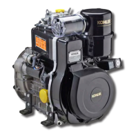
Piston ring, mounting order
A = 1° ring (internal tapered and torsional)
B = 2° ring (internal tapered and torsional)
C = 3° Oil control ring
D = Chrome-plated area
E = Chrome-plated area
Note:
When there is writing on the surface of a piston ring,
mount that surface with face upward.
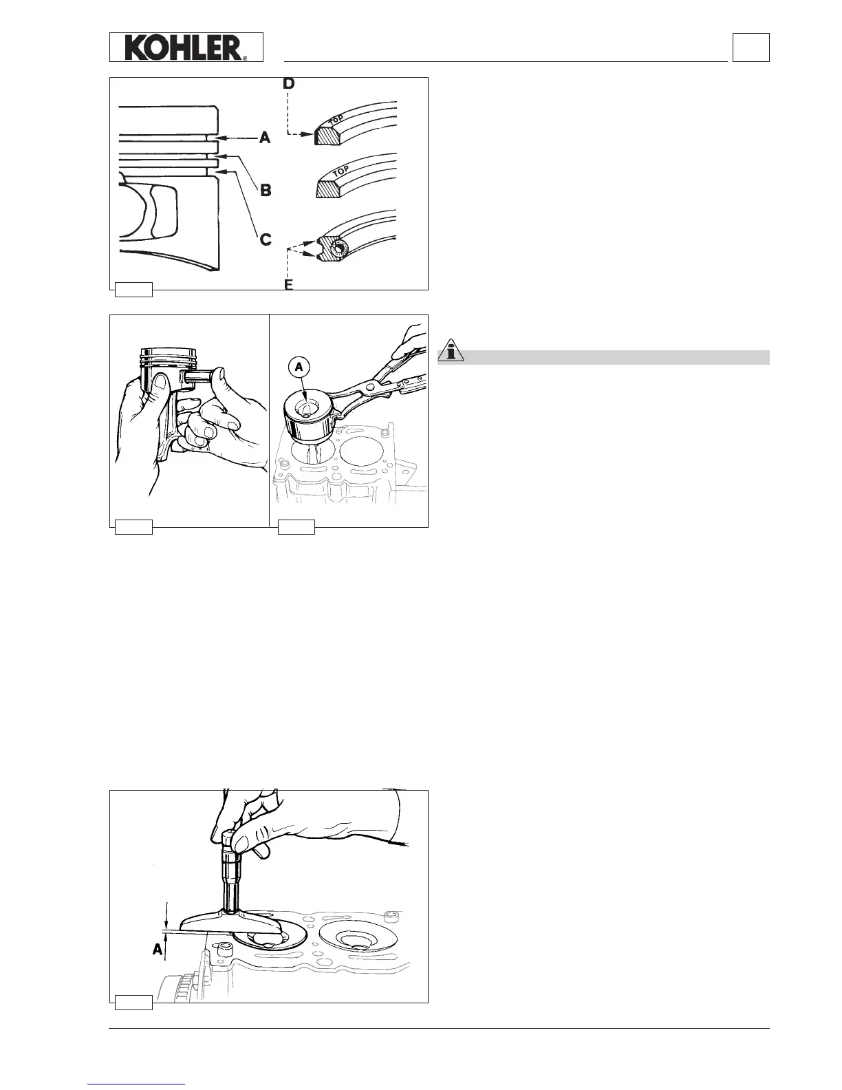
Piston clearance
The piston in the TDC (top dead centre) position may extend or
be short of the upper surface of the cylinder.
Determinare the clearance of each piston using a dial indicator
to measure the difference between the two surfaces (piston
crown and upper cylinder surface).
To determine the piston clearance and, by consequence, which
copper gaske is most suitable it is necessary to consider the A
value of the piston that projects furthest.
Piston, assembly
Important
Before re-mounting lubricate the piston pin, piston,
cylinder and conncecting rod big end bearing.
Couple the piston to the connecting rod inserting the pin, after
lubricating it, just via thumb pressure.
Insert the two pin stop rings and check that they are properly
housed in their seats (see g. 101).
Using piston ring compression pliers, introduce the piston into
the cylinder so that combustion chamber A is directly under the
precombustion chamber parallel to the head.
Couple the piston/connecting rod to the crankshaft.
For tightening the head/connecting rod see g. 115-116.
Disassembly / Reassembly

 Loading...