- 90 -
KD 702_1003_1404 Workshop Manual_cod. ED0053029340_1° ed_ rev. 00
182
183
10
Injection advance control and regulation
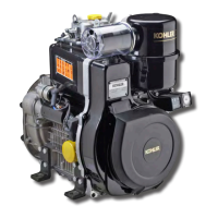
- Dismount the rocker arm cover (see page 52).
- Position the device on the head, in contact with cylinder no. 1.
- Mount the dial gauge on the valve controlled by tool ref.
1460.048.
- Via lever 1 of the tool, open the valve until it comes into
contact with the piston.
- Then rotate the crankshaft until the TDC is read in the dial
gauge. Then reset the hundredths.
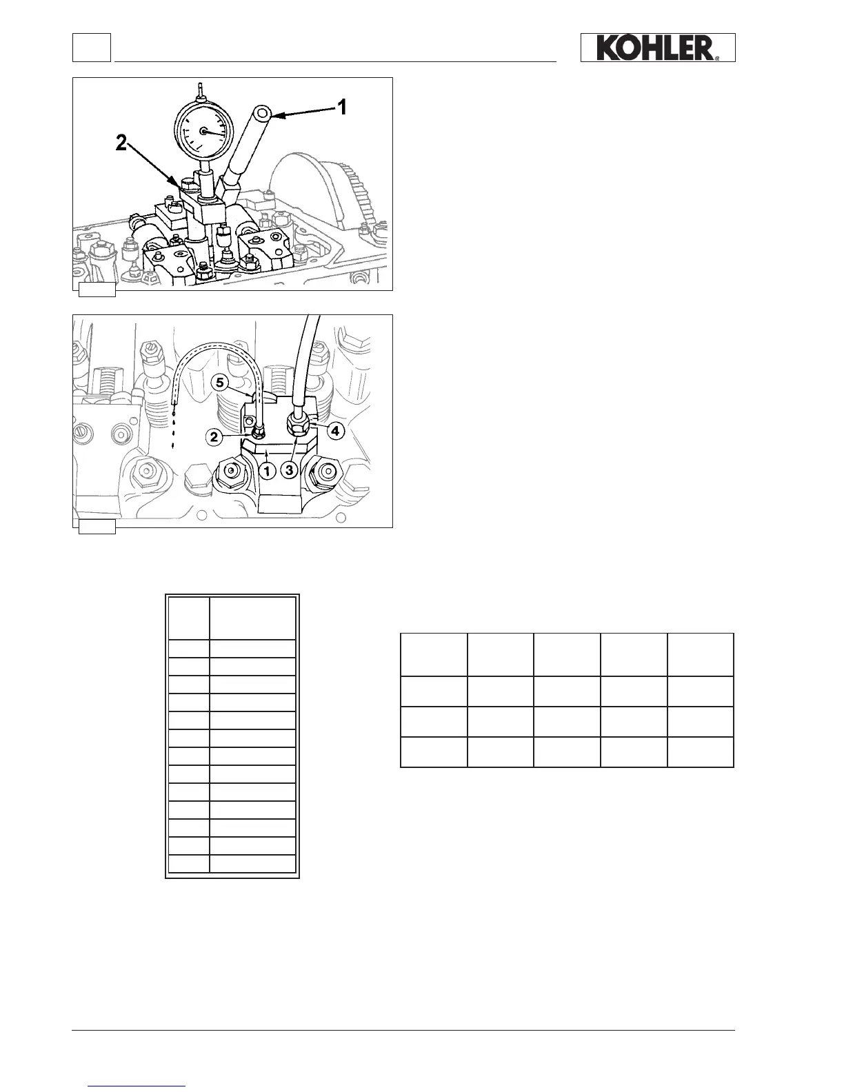
- Remove the fuel pipes.
- Remove the O-ring in contact with the non-return valve and
replace it with the appropriate gasket - equipment component
part ref. 1460.074. Once the check has been completed,
remove the gasket and ret the O-ring.
Connect tool 1460.074 on pump n° 1. This will automatically
position the control lever to the maximum delivery. The tool is
provided with 3÷4 couplings for connection to a tank that must
be not lower than 30 cm from the pumps level. Coupling 2 is
equipped with a plastic pipe 5 with internal drip collecting wire.
- Put cylinder 1 under compression and open the tank tap. Fuel
diesel will start to ow out from coupling 2.
- Slowly rotate the engine towards TDC 1 until the diesel fuel
stops leaking out.
- At this point with lever 1 (of g. 182) move again the valve
until it touches the piston and read on the dial gauge how
many hundredths are missing from the previously reset value
(TDC).
- To convert hundredths into degrees, consult the table below.
- Repeat the operation on the other cylinders.
Injection advance for currently used pump/injector unit
* With aluminuim crankcase
Engine Code Reference n° Rpm
Fuel system
a
KDW
702-1003-1404
mm
18° 2.468
17° 2.205
16° 1.956
15° 1.721
14° 1.501
13° 1.296
12° 1.105
11° 0.930
10° 0.769
9° 0.623
8° 0.793
7° 0.378
6° 0.277
a
702-1003
1404
6590.290 235-4 1500÷2999 8°÷10°
702-1003
1404
6590.290 235-4 3000÷3600 12°÷14°
702-1003
1404
6590.290 235-4 > ÷3600 13°÷15°

 Loading...