TP-5867 11/0244 Section 6 Component Testing and Adjustment
Component
Ohmmeter
Connections
Ohmmeter
Scale
Generator Set
Master Switch
Position
Ohmmeter Readings for Operative
Components*
Generator set master
switch
P1-2 (47) and P1-14 (N) R x 1000 RUN Zero ohms (continuity). Any other reading
indicates a defective switch.
OFF/RESET No reading (open circuit). Any other
reading indicates a defective switch.
Hourmeter (+) and (--) terminals Rx1 OFF/RESET Continuity (low resistance). If no
continuity is found, replace the hourmeter.
P1 wiring harness P1-14 and ground Rx1 OFF/RESET Zero ohms (continuity)
Any other reading indicates a poor ground
connection.
P1-12 and P1-15 (stator
leads 1 & 2, 1 phase)
Rx1 OFF/RESET Zero ohms (continuity).
Controller 10-amp fuse and
wiring
P1-10 and battery positive
(+) cable
R x 100 OFF/RESET Zero ohms (continuity). If no continuity is
found, check for an open circuit and/or a
blown fuse.
Voltage regulator circuit
10 amp fuse
P10-5 and stator lead 55 at
the fuse holder (relay
controller)
R x 100 OFF/RESET Zero ohms (continuity). If no continuity is
found, check for an open circuit and/or a
blown fuse.
Low oil pressure switch* Lead 13 and ground
(engine block)
R x 1000 OFF/RESET Zero ohms (continuity). No continuity
indicates a defective switch and/or wiring.
High engine temperature
switch
Lead 37 and ground
(engine block)
R x 1000 OFF/RESET No reading (open circuit). Any other
reading indicates a defective switch.
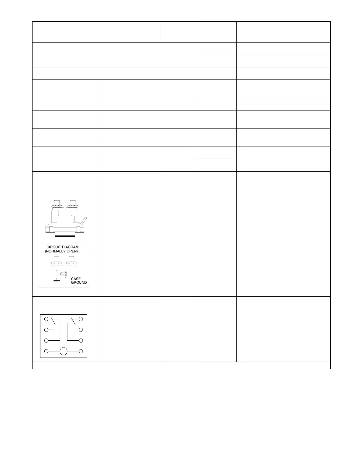
Starter relay
(See illustration below)
Starter relay terminal and
relay base (ground)
Rx1 OFF/RESET 5--6 ohms. Lower resistance indicates a
shorted relay coil and/or wiring. High
resistance indicates an open relay coil
and/or wiring.
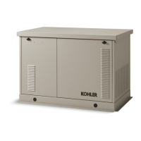
Cyclic crank relay and
wiring
C
78
56
34
12
Disconnect the relay and
remove it from the
controller. Connect the
ohmmeter to relay
terminals 7 and 8.
Rx1 — 160 ohms
* See Section 6.8, Fault Shutdown Test Procedure
Figure 6-15 Continuity Checks