TP-5867 11/02 67Section 8 Disassembly/Reassembly
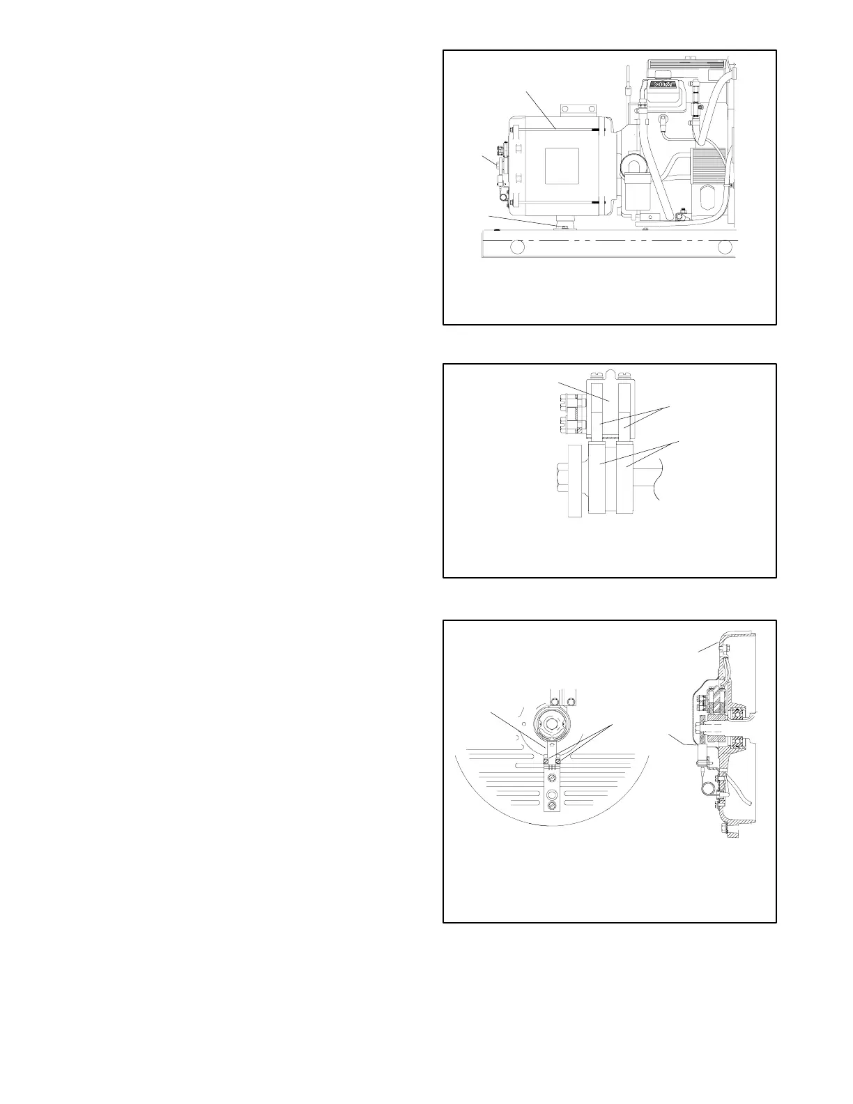
b. Reinstall the screws and washers that secure
the alternator frame vibromount mounting plate
to the generator set skid. See Figure 8-12.
5. Tighten the hardware to the specified torques.
a. Tighten the rotor thrubolt to 28 ft. lb. (38 Nm). It
may be necessary to keep the engine flywheel
from turning while torquing the rotor thrubolt.
See Figure 8-12.
b. Tighten the four alternator assembly overbolts
to 60 in. lb. (7 Nm). See Figure 8-12.
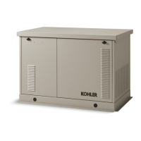
6. Reinstall the end bracket components.
a. Install the brush holder onto the end bracket.
Verify that the brushes are not sticking in the
holder.
b. Verify that the brushes are centered on the slip
rings. If required, insert spacers between the
mounting surface and brush holder to center
the brushes on the slip rings. See Figure 8-13.
See Section 6.6, Brushes, for more
information.
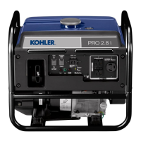
c. Set the gap between the magnetic actuator and
the speed sensor to 0.010-0.020 in.
(0.25-0.51 mm) and final tighten the sensor
mounting screws. See Figure 8-14.
d. Reconnect the white (0), red (+), and black (--)
speed sensor leads to the speed sensor
terminals.
e. Reinstall the brush cover onto the alternator
end bracket. Verify that the brush leads are not
pinched between the brush cover and end
bracket.
A-358000A-B
1
2
3
1. Alternator assembly overbolts
2. Rotor thrubolt
3. Alternator vibromount plate mounting hardware
Figure 8-12 Generator Set, Right Side
5632716
1
2
3
1. Brush holder
2. Brushes
3. Slip rings
Figure 8-13 Brush Positioning
P-358000B-M
1
4
2
1. Speed sensor
2. Speed sensor mounting screws and washers
3. End bracket
4. Speed sensor gap
X--67--113 (4)
3
Figure 8-14 Speed Sensor Assembly