EasyManua.ls Logo

Kohler Curtis F Series User Manual

Kohler Curtis F Series
277 pages
To Next Page IconTo Next Page
To Previous Page IconTo Previous Page
Page #125 background imageLoading...
Page #125 background image
4 — PROGRAMMABLE PARAMETERS
pg. 117
Return to TOC Curtis AC F2-A, F4-A, F6-A Motor Controllers – FOS 4.5 – April 2022
CONTROLLER SETUP — INPUTS MENU, cont’d
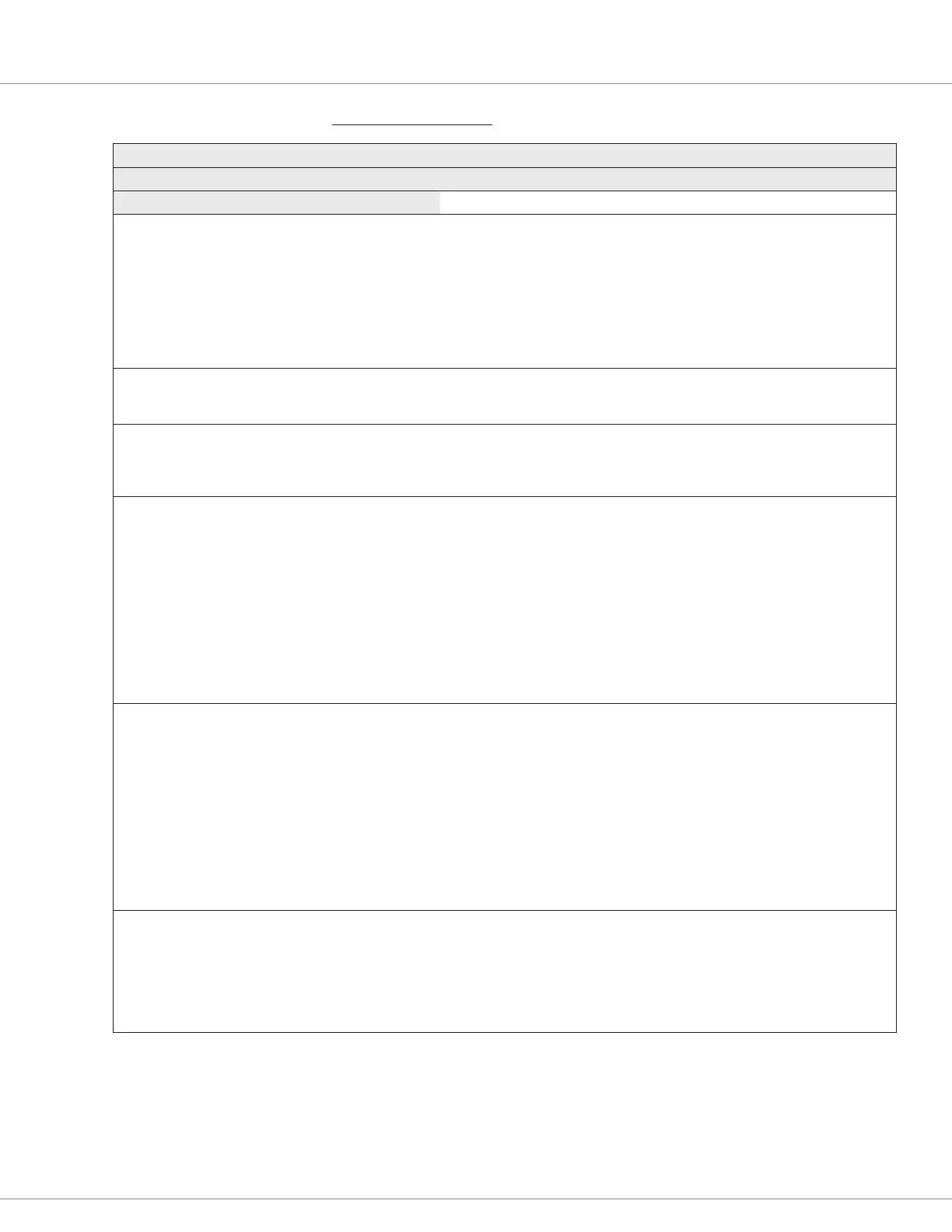
PARAMETER ALLOWABLE RANGE DEFAULT DESCRIPTION
Analog 18 menu
Parameters for Voltage with Supply selection
Analog 18 Type
Analog_Input_18_Type
0x330F 0x00
Voltage with Supply
(selection menu)
The Analog 18 Type “Voltage with Supply” selection operates the
Analog 18 input as a raw voltage at the pin with an internal pull-
up supply voltage.
The pin’s output voltage is 10V (approx.) with a 3 mA current limit
(to the external load/device). Reference Table 10.
Use this selection for operating resistive devices such as
thermistors and photocells and reading the voltage in VCL using
the Monitor variable analog_input_volts_18 (0x3B60), then
processing the value in the VCL program.
Voltage
Analog_Input_Volts_18
0x3B60 0x00
–327.68 – 327.67V
–32768 – 32767
Read Only The analog voltage at the analog 18 input (Input 18).
Percent
Analog_Input_Percent_18
0x3B62 0x00
0.0 – 100.0 %
0 – 1000
Read Only The percentage of the voltage at pin 17 based upon the High and
Low settings, i.e., the percent of:
[(analog_input_volts_18) – (analog_input_18_low)] /
[(analog_input_18_high) – (analog_input_18_low)]
Low
Analog_Input_18_Low
0x3309 0x00
0.0 – 11.0V
0 – 1100
0.0V The minimum input voltage before a fault is declared. When the
Analog 18 Type selection is Voltage with Supply, this set point
represents the 0% point for the normalized input.
Faults:
When the voltage falls below this parameter, it will trigger
the Analog_18_OUT_OF_RANGE fault (flash code 0xBD, CAN
Index 0x262B).
If assigning the Throttle to Analog 18, the resulting fault will
become the Throttle Input fault (flash code 0x42, CAN Index
0x2210) if Throttle_Source = 18.
If assigning the Brake to Analog 18, the resulting fault will become
the Brake Input fault (Flash code 0x44) if Brake_Source = 18.
High
Analog_Input_18_High
0x330A 0x00
0.0 – 11.0V
0 – 110
5.1V The maximum input voltage before a fault is declared. When the
Analog 18 Type selection is Voltage with Supply, this set point
represents the 100% point for the normalized input.
Faults:
When the voltage rises above this parameter, it will trigger
the Analog_18_OUT_OF_RANGE fault (flash code 0xBD, CAN
Index 0x262B).
If assigning the Throttle to Analog 18, the resulting fault will
become the Throttle Input fault (flash code 0x42, CAN Index
0x2210) if Throttle_Source = 18.
If assigning the Brake to Analog 18, the resulting fault will become
the Brake Input fault (Flash code 0x44) if Brake_Source = 18.
Fault Tolerance
Analog_Input_18_Fault_
Tolerance
0x337A 0x00
0.0 – 11.0V
0 – 1100
0.0V Species the voltage threshold above the congured high limit
or below the low limit, exceeding this results in an analog out of
range fault.
For example, if High = 9.6V, Low = 1V and Tolerance = 0.2V, an
input voltage between 1V to 9.6V is mapped to 0–100%.
Voltages above 9.8V (9.6 + 0.2) or below 0.8V (1V – 0.2V) trigger
the fault.
Quick Links:
Voltage rottle p.166
3-Wire rottle p.165
2-Wire rottle p.165
Fig. 13 p.17
Table 10 p.24

Table of Contents

Question and Answer IconNeed help?

Do you have a question about the Kohler Curtis F Series and is the answer not in the manual?

Kohler Curtis F Series Specifications

General IconGeneral
BrandKohler
ModelCurtis F Series
CategoryController
LanguageEnglish

Summary

1 — OVERVIEW

HOW TO USE THIS MANUAL

Guidance on navigating and utilizing the manual's content for effective controller application.

WHAT IS NEW IN FOS 4.5.0.0 ... HIGHLIGHTS

Summary of key enhancements and changes in the FOS 4.5.0.0 firmware version.

GETTING THE MOST OUT OF YOUR CURTIS CONTROLLER

Advice on optimizing controller application through understanding manual sections and tools.

2 — INSTALLATION AND WIRING

PHYSICALLY MOUNTING THE CONTROLLER

Instructions for proper physical installation and mounting of the controller for optimal performance and environmental protection.

PRECAUTIONS

Essential safety and design considerations for ensuring EMC compliance and preventing electrical issues.

HIGH CURRENT CONNECTIONS

Details on connecting high-current terminals (B+, B-, U, V, W) and recommended connection guidelines.

LOW CURRENT CONNECTIONS

Information on logic and low-power connections via AMPSEAL connectors, including pin assignments.

Rotor Position feedback

Guidance on wiring rotor position sensors, including signal wiring best practices and shielding.

CANbus

Best practices for CANbus wiring, including twisted-pair and shielded cable usage for reliable communication.

All other low power wiring

Recommendations for routing low-power wiring to avoid signal interference and protect against damage.

Protected voltages

Information on protected voltage ratings for low-power pins and crucial connection warnings to prevent damage.

3 — APPLICATION-SPECIFIC FEATURES

MOTOR SPEED CONSTRAINTS

Details on how electrical frequency, encoder pulses, and parameter settings limit maximum motor speed (RPM).

VOLTAGE LIMITS

Explanation of hardware and parameter-based voltage limits, including operating regions and thresholds.

BROWNOUT VOLTAGE

Information on the fixed brownout voltage level and controller actions when voltage falls below this threshold.

KSI AND B+ INPUT

Notes on KSI input connection to B+ terminal for controller power, precharge, and BDI usage.

BATTERY DISCHARGE INDICATOR

Explanation of the BDI algorithm for calculating battery state-of-charge (SOC) and its viewable parameters.

4 — PROGRAMMABLE PARAMETERS

PROGRAMMING MENUS

Overview of programmable parameters organized into nested menus for customization via CANbus connection.

PARAMETER CHANGE FAULTS [PCF]

Explanation of faults triggered when parameters are changed while the motor bridge is enabled.

MONITOR VARIABLES WITHIN PARAMETER MENUS

Information on specific monitor variables contained within parameter menus, which are read-only.

PROGRAMMING TOOLS

Details on PC-based Curtis Integrated Toolkit (CIT) and the Curtis 1313 handheld programmer.

5 — SYSTEM MONITOR MENU

MOTOR MENU

Displays real-time motor data including RPM, temperature, torque, power, and feedback signals.

VEHICLE MENU

Monitors vehicle speed, odometer, acceleration, and distance traveled, configurable in metric or English units.

FAULT HISTORY

Accesses and clears the controller's fault history file for diagnosing and verifying problem resolution.

6 — COMMISSIONING

INITIAL SETUP

Essential steps for setting up controller parameters and ensuring they are suited to the specific application.

TRACTION MOTOR SELECTION

Guidance on selecting and commissioning ACIM or PMAC motors, including compatibility and procedures.

AC Motor Characterization

Procedure for characterizing ACIM traction motors using a quadrature encoder or Sin/Cos sensor.

AC MOTOR TUNING GUIDE

Steps for tuning the AC traction motor performance by selecting control modes and adjusting parameters.

SETTING UP THE HYDRAULIC SYSTEM

Procedures for setting up hydraulic systems, including lift, lower, and load-hold valve controls.

7 — DIAGNOSTICS AND TROUBLESHOOTING

THE DIAGNOSTICS PROCESS

Methods for obtaining diagnostics information, including status indicators, programmer tool, and CAN emergency messages.

FAULT ACTIONS

Table detailing fault actions taken by the controller, including shutdown sequences and VCL references.

8 — MAINTENANCE

CLEANING

Procedure for routine cleaning of the controller exterior to protect against corrosion and electrical issues.

FAULT HISTORY

Accessing and clearing the controller's fault history file to diagnose and verify problem resolution.

APPENDIX A

CAN PDO MAP SETUP

Guidance on setting up PDO maps for F-Series controllers using the Curtis Integrated Toolkit™ for CAN communication.

APPENDIX B

ELECTROMAGNETIC COMPATIBILITY (EMC)

Information on emissions and immunity, and techniques to reduce EMC problems in products with Curtis controllers.

ELECTROSTATIC DISCHARGE (ESD) IMMUNITY

Necessary precautions to protect ESD-sensitive components from damage by providing sufficient distance or isolation.

DECOMMISSIONING AND RECYCLING THE CONTROLLER

Instructions for decommissioning and recycling the controller, following OEM and landfill directives.

APPENDIX C

EN 13849 COMPLIANCE

Overview of safety requirements and performance levels (PL) according to EN13849 for control systems.

APPENDIX D

CURTIS INTEGRATED TOOLKITTM

Description of CIT software for configuring and communicating with Curtis Instruments products via CAN network.

Choosing the CAN Interface Device Driver

Steps to select and install the appropriate CAN dongle driver for PC communication with the controller.

Creating a Project with a new F-Series controller

Step-by-step guide to opening the Project Explorer and creating a new project for F-Series controller configuration.

APPENDIX E

SPECIFICATIONS: CONTROLLER

Detailed specifications for AC F6-A, F4-A, and F2-A controllers, including electrical and mechanical data.

Related product manuals