4 — PROGRAMMABLE PARAMETERS
pg. 69
Return to TOC Curtis AC F2-A, F4-A, F6-A Motor Controllers – FOS 4.5 – April 2022
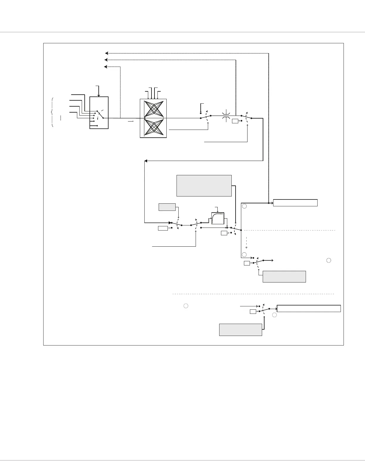
Figure 23
Brake Signal Processing
Mapped_Brake
Bold = Parameter
Italics = VCL Variable
BoldItalics = Monitor Variable
Forward
Reverse
Brake Min Input
Brake Map Shape
Brake Max Input
Brake (Regen) Mapping
Brake Offset
Brake_Command
Brake Input
Analog1
Analog6
Analog18
Analog19
Brake Source
VCL_Brake_Pot
0
Brake_Pot_Percent
* Brake Pedal using Potentiometer Inputs
*
Pin No.
27
IO Assignments /
Controls Menu
%
%
0
100
100
0
VCL_Brake
100%
0%
VCL_Brake_Enable= On
0%
Brake_Pedal_Enable = On
To Motor Control Processing
100%
FULL BRAKE
Fault Action
1% > Mapped_Brake < 90%
FILTER
Brake Filter
YES
NO
0%
Dual_Drive_Brake_from_Manager
0%
Interlock = On
Dual Drive Mode Type = On
Dual Ancillary Motor = Off
Control Mode = 0 or 1
EMR = Enabled
EMR Switch = Active
EMER_REV_TIMEOUT Fault = True (set)
NOT Interlock Sequence Timeout
A
B
To DD Ancillary Motor Control Processing
Interlock = On
Dual Drive Mode Type = On
Dual Ancillary Motor = On
A
Dual Drive Brake Signal Chain. Manager Controller processing
Single Motor Controller (default)
Dual Drive, Manager Controller (if applicable)
0%
Dual_Drive_Brake_From_Manager
C
...
C
...
Dual Drive Brake Signal Chain ... Ancillary Controller
Dual Drive, Ancillary Controller

 Loading...


