6 — COMMISSIONING
pg. 171
Return to TOC Curtis AC F2-A, F4-A, F6-A Motor Controllers – FOS 4.5 – April 2022
Hall-eect voltage throttles
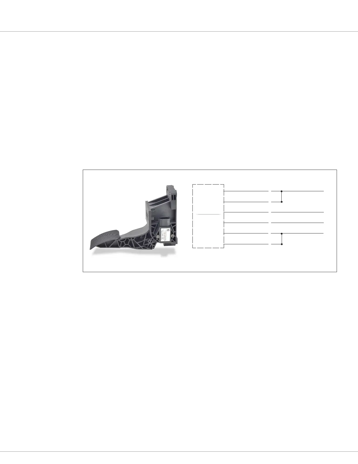
e Curtis FP Series of electronic throttles oers multiple pedal angles and mounting congurations
(oor, suspended, ush) with 0–5 Volt operation and an Idle Validation Switch (IVS). e IVS will
connect to an assigned analog input (e.g., pin 16). See Figure 38 (35-pin controller basis).
e Curtis ET-XXX (e.g., ET-126) electronic throttle is typically a drive throttle (as illustrated in
Figure 39). When used in Class III tiller handles or twist-throttle grips, it oers symmetrical throttle
response in both the forward and reverse directions of the twist-grip/ippers (i.e., CW and CCW
rotation). Based upon rotation it switches the forward or reverse switches to KSI and thus provides the
directional switches within the throttle assembly. It is a wigwag type throttle, which when released,
returns the throttle to neutral for convenience and safety. Other, similar third party wigwag throttles
follow the same setup process.
e ET-XXX voltage throttles contain no built-in fault detection, or a throttle validation signal. It is
the responsibility of the OEM to provide appropriate throttle fault detection.
THROTTLE SENSOR OUTPUT (0.5 –4.5V)
IVS OUTPUT (0.75V [5-0V])
HALL-EFFECT
THROTTLE
S E NSO R
I/O Ground (pin 7)
Voltage (analog 1) input (pin 16)
(1) Sensor +5V supply
(2) Ground
(3) IVS Signal (voltage)
(4) Throttle Signal (voltage)
(5) IVS Ground
(6) IVS +5V supply
>>
>>
>>
>>
>>
>>
+5V (pin 26)
Voltage (analog) input (pin TBD)
IDLE-VALIDATION
SWITCH
Figure 38
Curtis FP-SCV-0022
Hall-eect rottle
Voltage rottle setup
Wire the voltage throttle as illustrated in the options shown in Figures 38 and 39. With the throttle
connected and powered, set the Low and High parameters based upon the observed input Voltage
(analog_input_volts_1) while moving the throttle throughout its physical range (stroke). ese
parameters set the range for 0% (Low) and 100% (High) throttle. Inputs below and above these set
points will declare a fault. e Percent (Analog_Input_Percent_1) monitor variable is repeated as
rottle Input (rottle_Pot_Percent) in the Application Setup » rottle menu. Use either of these
variables as feedback when adjusting the potentiometer throttle’s Forward & Reverse Min/Max
Input parameters (described below).
For voltage throttles with an idle validation switch or additional voltage outputs, program these
signals as per their type using the controller’s available switch or analog inputs. Reference the
wiring diagrams and Tables 8 and 9 for these available switch and analog inputs. Be sure to include
these additional signals in a VCL program as the means to integrate such throttle validation signals
into the controller application.
Note: e pin numbers in Figures 36–39 are on the 35-pin controller basis.
Quick Links:
Table 8 (Switch Inputs) p.20
Table 9 (Analog Inputs) p.22

 Loading...


