2 — INSTALLATION AND WIRING
pg. 21
Return to TOC Curtis AC F2-A, F4-A, F6-A Motor Controllers – FOS 4.5 – April 2022
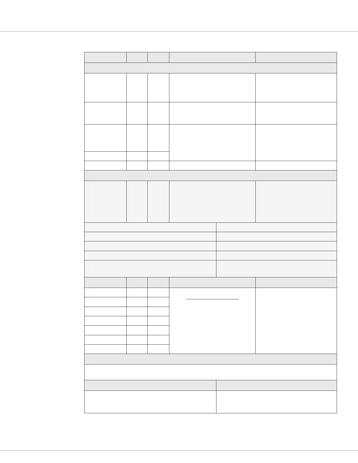
Signal Name 23-Pin 35-Pin Logic Threshold
1
Input Impedance
AVAILABLE/ALTERNATIVE SWITCH (DIGITAL) INPUTS
Switch 1 11 16
(Throttle Wiper, typical usage)
Rising edge = 4V max
Falling edge = 1V min
(Low/Off (pulled to B–)
> 20k Ω
Switch 2 9 8
(motor temp sensor, typical usage)
Internal pull-up
(A connection to I/O Gnd is < 2 mA)
Based upon usage.
Contact Curtis.
Switch 3 17 31
(Motor Position Sensor, typical usage)
Rising edge = 4V max
Falling edge = 1V min
(Low/Off (pulled to B-)
As Encoder:
5k Ω
As Sin/Cos Sensor:
> 50k Ω
Switch 4 18 32
Switch 6 10 15 (Pot 6 Supply, typical usage) > 20k Ω
AVAILABLE/ALTERNATIVE SWITCH (DIGITAL) PWM INPUT
Switch 10 N/A 10
Selectable Low to High Frequency:
500 – 10,000 Hz
Selectable Low to High Duty Cycle:
0 – 100%
Ability to monitor selection as a
percentage of settings.
See Switch 10, above
Frequency Measurement Range 500Hz – 10kHz
Frequency Measurement Accuracy ± 1%
Duty Cycle Measurement Range 10-90%
2
Duty Cycle Measurement Accuracy ± 1%
Fault Diagnostics • Input frequency out of congurable min/max limits
• Input duty-cycle out of congurable min/max limits
Signal Name 23-Pin 35-Pin Logic Threshold
2
Input Impedance
Switch 21 7 2 (Coil Drivers, typical)
Rising edge = 8V max
Falling edge = 1V min
(Low/Off (pulled to B–)
> 30k Ω
(800 uA leakage current
at nominal voltage)
Switch 22 4 5
Switch 23 5 4
Switch 24 6 3
Switch 25 3 6
Switch 26 n/a 19
Switch 27 n/a 20
SWITCH CLEANING CURRENT
≥ 2.0 mA at nominal battery voltage (24V model)
≥ 1.3 mA at lowest nominal battery voltage (36-48V model)
VCL Functions VCL Monitor Variables
Enable_Emer_Rev( )
Disable_Emer_Rev( )
Setup_4p_Select( )
Switch_X (X = Switch#) [as assigned in Programmer]
Any of the applicable, lift, lower, interlock, EMR input
active, etc.
1
Logic thresholds are adjustable. See I/O parameter settings in Application and Controller Setup menus.
2
The ability to measure duty cycles near 0% or 100% is a function of the voltage/frequency of the applied signal and the input
capacitance that is added for protection against ESD. Lower input frequencies can allow reading closer to 0%/100% duty cycles.
Test each application in its actual operating environment and implement with an acceptable margin of error.
Table 8 Digital (Switch) Inputs Electrical Specifications, cont’d

 Loading...


