TP-6833 2/16 15Section 2 Installation
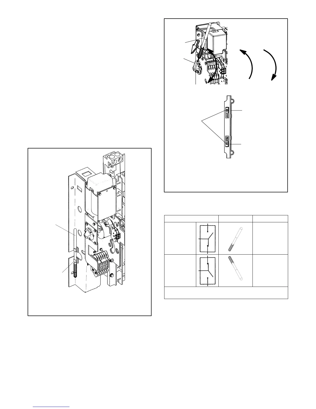
3. 225--600 amp switches: See Figure 2-5. Insert
the maintenance handle into the hole in the shaft on
the left side of the operator.
800--1200 amp switches: See Figure 2-7. Insert
the maintenance handle into the hole in the molded
hub on the left side of the operator.
4. Move the maintenance handle up or down as
shown to manually operate the transfer switch. It
should operate smoothly without any binding. If it
does not, check for shipping damage or
construction debris. See Figure 2-6.
5. Return the transfer switch to the Normal position.
6. Remove the maintenance handle and store it on the
frame in the clips provided.
Note: Verify that the maintenance handle has been
removed before proceeding.
202
1. Maintenance handle
2. Storage clip(s)
1
2
Figure 2-4 Detachable Handle Storage (typical)
3
283
1. Handle
2. Hub
3. Position indicators (right side of contactor):
O = open, C = closed
1
2
N
E
N
E
Figure 2-5 Manual Operation, 225--600 Amp
Model KCS
ATS Position
Handle Indicators
Normal
Up
E:O
upper contacts open
N:C
lower contacts closed
Emergency
Down
E:C
upper contacts closed
N:O
lower contacts open
Note: If Normal and Emergency connections are reversed,
this operation is also reversed.
Figure 2-6 Maintenance Handle Positions,
225-- 1200 Amp Model KCS