TP-6833 2/16 31Section 2 Installation
2.9.4 Auxiliary Contacts
Connect the auxiliary contacts to customer-supplied
alarms, remote indicators, or other devices. Auxiliary
contacts provide contacts that close when the transfer
switch is in the Normal position and contacts that close
when the transfer switch is in the Emergency position.
Refer to the wiring diagrams provided with the transfer
switch for auxiliary contact connection information.
Figure 2-34 lists the number of contacts available by
ATS model and size (amps). See Figure 2 -35 through
Figure 2-37 for contact locations.
Follow the wire size and tightening torque specifications
shown on the decal on the transfer switch.
Auxiliary Position Indicating Contacts
(rated 10 amps @ 32 VDC/250 VAC)
Switch
Rating, amps
Number of Contacts Indicating
Normal, Emergency
Number of Contacts Indicating
Normal, Emergency
KCS KCP KCC
30--150 2, 2 — —
150--230 2, 2 8, 8 8, 8
230 (600 V) 8, 8 8, 8 8, 8
260--600 8, 8 8, 8 8, 8
800-1200 8, 8 8, 8 8, 8
1600--4000 8, 8 7, 7 7, 7
Figure 2-34 Auxiliary Contacts
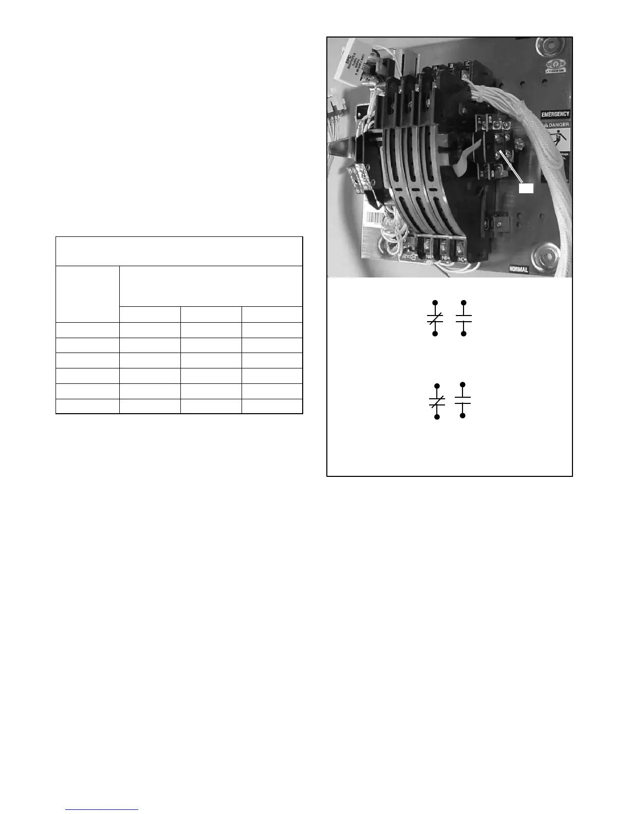
1
1. Auxiliary contacts 10--13 and 29--32 (contacts shown with
contactor in Normal position)
6126
GM46278
12
13 11
10
31
32 30
29
Figure 2-35 Auxiliary Contacts, 30--230 Amp Transfer
Switches