TP-6833 2/16 17Section 2 Installation
2.6 Manual Operation, Model KCP
Programmed-Transition
Switches
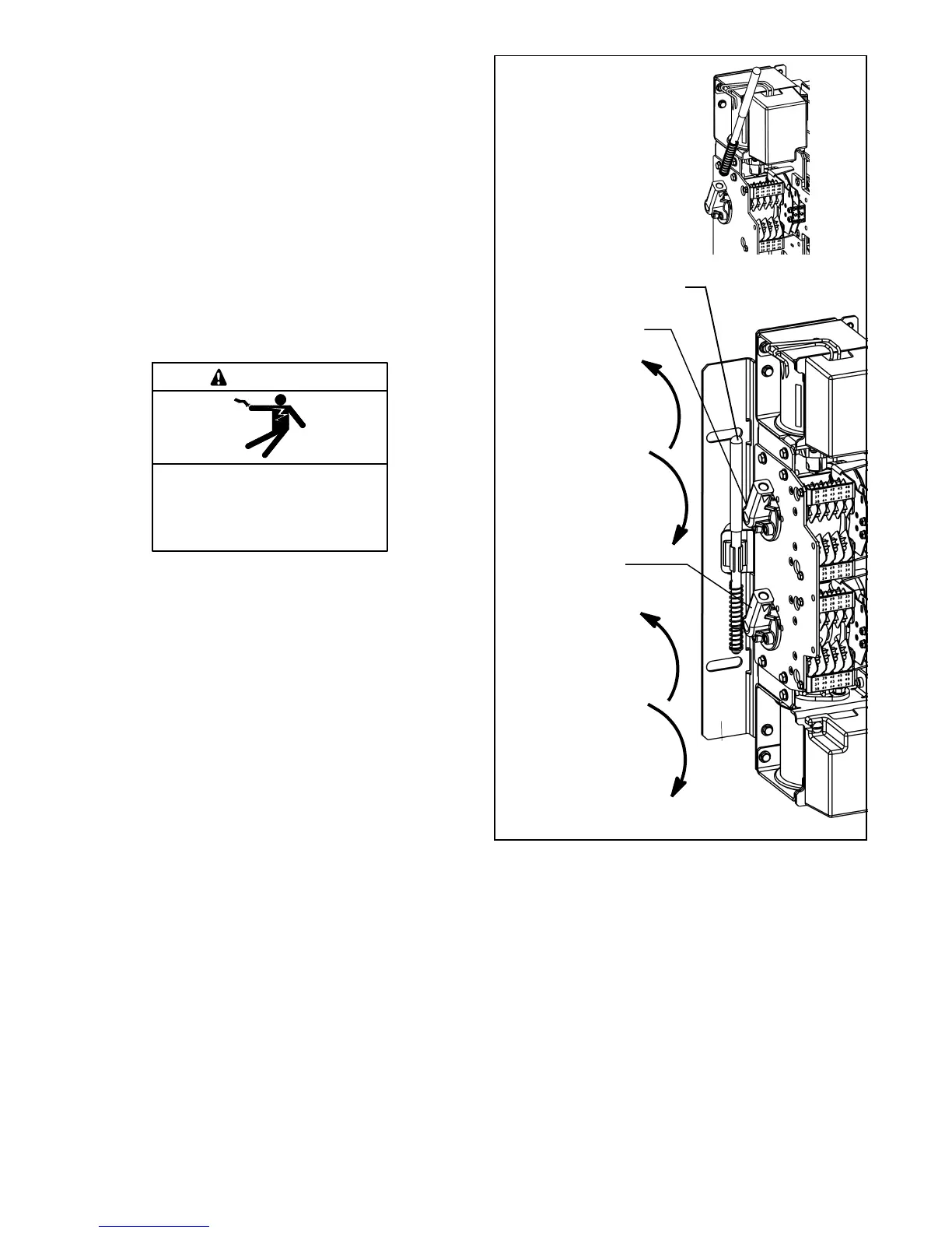
Programmed-transition switches have two operators,
Normal and Emergency, on the left side of the contactor
assembly. Mechanical interlocks prevent closing both
operators at the same time. Refer to Figure 2-9 for
typical locations of the Normal and Emergency
operators.
Programmed-transition models use a detachable
manual operating handle. Position indicators on the
right side of the contactor assembly show the positions
of the operators. See Figure 2-10.
Hazardous voltage.
Will cause severe injury or death.
Disconnect all power sources before
opening the enclosure.
DANGER
Servicing the transfer switch. Hazardous voltage can
cause severe injury or death. Deenergize all power sources
before servicing. Turn off the main circuit breakers of all
transfer switch power sources and disable all generator sets
as follows: (1) Press the generator set off/reset button to shut
down the generator set. (2) Disconnect power to all battery
chargers. (3) Disconnect all battery cables, negative (--) leads
first. Reconnect negative (--) leads last when reconnecting the
battery cables after servicing. Follow these precautions to
prevent the starting of generator sets by an automatic transfer
switch, remote start/stop switch, or engine start command
from a remote computer. Before servicing any components
inside the enclosure: (1) Remove all jewelry. (2) Stand on a
dry, approved electrically insulated mat. (3) Test circuits with a
voltmeter to verify that they are deenergized.
NOTICE
Improper operator handle usage. Use the manual operator
handle on the transfer switch for maintenance purposes only.
Return the transfer switch to the normal position. Remove the
manual operator handle, if used, and store it in the place
provided on the transfer switch when service is completed.
UP opens the
Emergency source
contacts
DOWN closes the
Emergency source
contacts
UPPER SHAFT
UP closes the
Normal source
contacts
DOWN opens the
Normal source
contacts
LOWER SHAFT
Emergency Operator
(shown open)
Normal Operator
(shown closed)
Insert the maintenance
handle into the hub.
Handle storage location
Figure 2-9 Model KCP Manual Operation (typical)