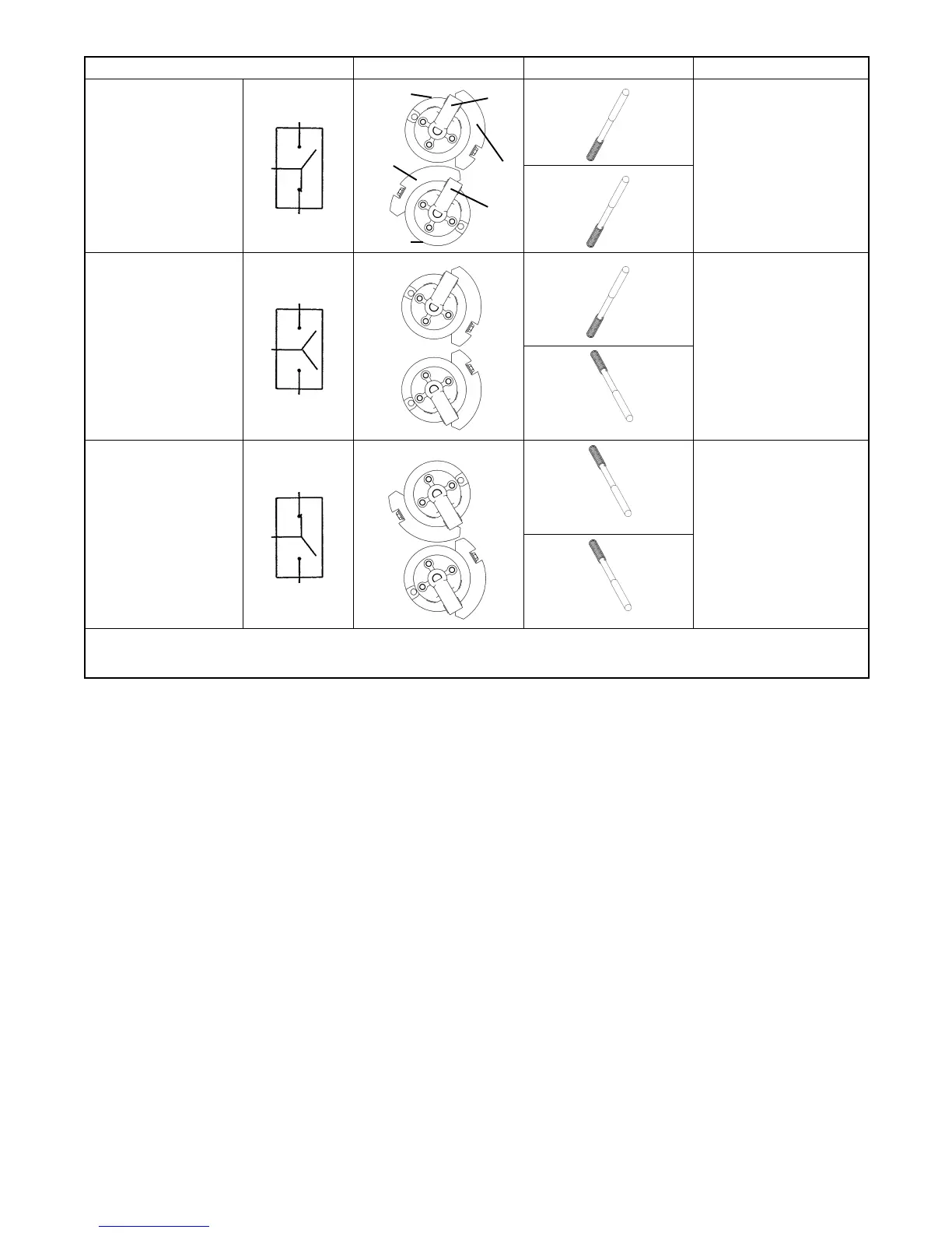
TP-6833 2/16 19Section 2 Installation
Transfer Switch Position Interlocked Weights Maintenance Handle Shaft Indicators
Normal
E
N
Lobe
Lob
Weight
Weight
Hub
Hub
Up
E:O
upper contacts open
N:C
lower contacts closed
Up
Load
Disconnected
E
N
Up
E:O
upper contacts open
N:O
lower contacts open
Down
Emergency
E
N
Down
E:C
upper contacts closed
N:O
lower contacts open
Down
Note: If Normal and Emergency connections are reversed this operation is also reversed.
Note: The lobes prevent closing both N and E contacts at the same time.
Figure 2-12 Maintenance Handle Positions, 800--1200 Amp Model KCP Only. ALL POWER MUST BE OFF !