TP-6833 2/1622 Section 2 Installation
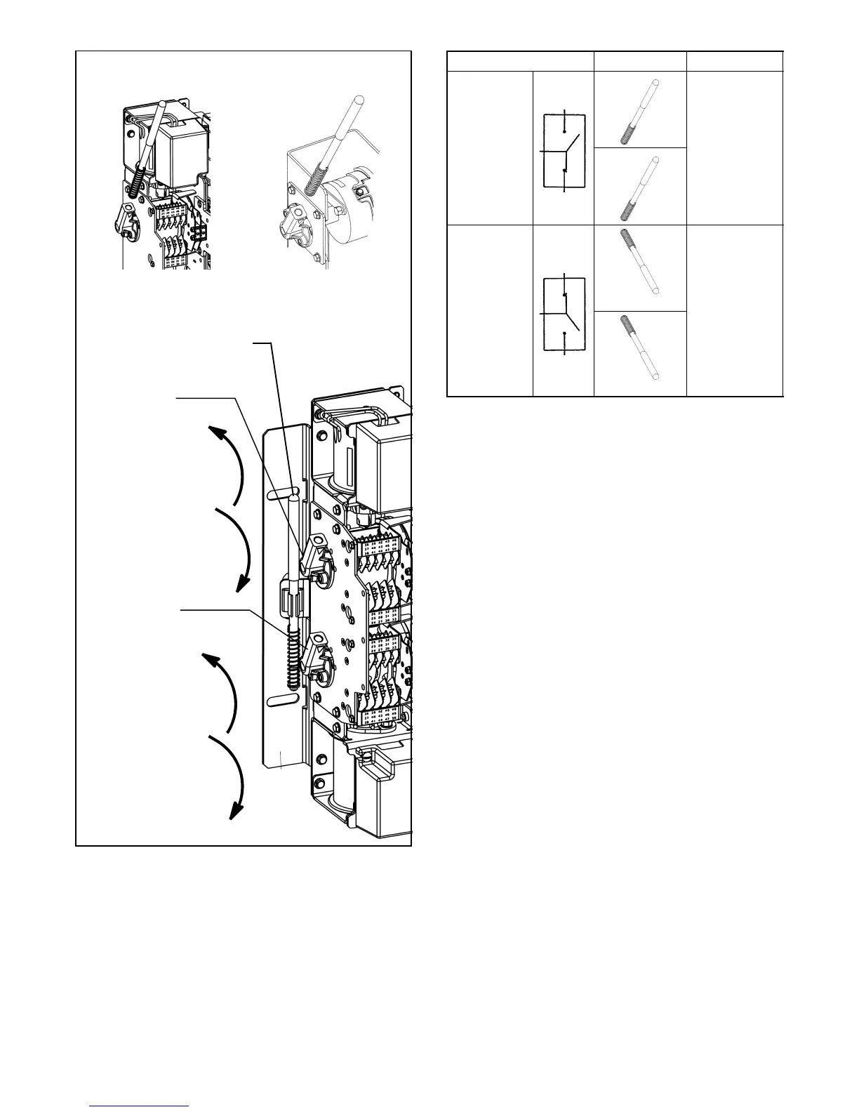
UP opens the
Emergency source
contacts
DOWN closes the
Emergency source
contacts
Upper Shaft
UP closes the
Normal source
contacts
DOWN opens the
Normal source
contacts
Lower Shaft:
EMERGENCY
OPERATOR
(shown open)
NORMAL
OPERATOR
(shown closed)
Insert the maintenance handle into the hub:
800--1200 Amps150--600 Amps
Handle storage location
Figure 2-15 Transfer Switch Manual Operation,
150 -- 1200 Amp Model KCC (typical)
ATS Position
Handle Indicators
Normal
E=O
upper contacts open
N=C
lower contacts closed
Emergency
E=C
upper contacts closed
N=O
lower contacts open
Figure 2-16 Maintenance Handle Positions, Model
KCC. ALL POWER MUST BE OFF !