TP-7070 7/1864 Section 2 Operation
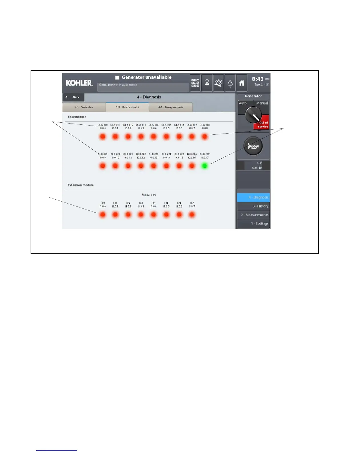
Screen 4.2--Binary inputs
The 4.2--Binary inputs screen is used to get a quick overview of the following logic states:
D Eighteen binary inputs for the base module
D Eight binary inputs for each remote module connected to the base module
1. Input number (DI A#10 to DI A#18 & DI B#19 to DI B#27)
2. Input status indicators: Red = 0 (input inactive); Green = 1 (input active)
3. Extension I/O module inputs appear here, if equipped
2
3
1
Red = Not Active (off)
Green = Active (on)
Figure 2-71 Binary Inputs Screen