TP-7070 7/18 65Section 2 Operation
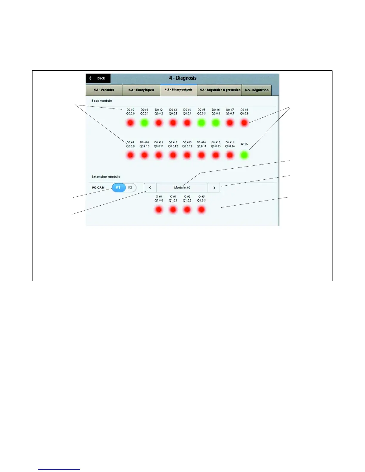
Screen 4.3--Binary outputs
The 4.3--Binary outputs screen is used to get a quick overview of the following logic states:
D Eighteen base module outputs
D Four outputs for each extension module connected to the base module
1. Output number (DO--#0 to DO--#8 &DO--#9 to DO--#16+ WDG *)
2. Output status indicators: Red = 0 (output inactive); Green = 1 (output active)
3. Number of the remote module (only appears if there is a single remote module)
4. Selection of remote module n+1
5. Output status indicators for optional I/O modules: Red = 0 (output inactive); Green = 1 (output active)
6. Selection of remote module n--1
7. Choice of CAN I/O bus (only appears if there is a single CAN bus )
* The output WDG (Watchdog) cannot be used.
6
2
7
3
4
1
Red = Not Active (off)
Green = Active (on)
5
Figure 2-72 Binary Outputs Screen
Module #0 is reserved for the optional Manual Key
Switch/Load Shed Module. Outputs #0 through #3
represent loads 1 through 4. When the output is
deactivated, the output indicator is red and the load is
connected. When an output is activated, the indicator
turns green and the load is shed. See Section 2.6 for
more information about the load shed function.