80 Electrical System and Sensor Troubleshooting TP-6903 5/16a
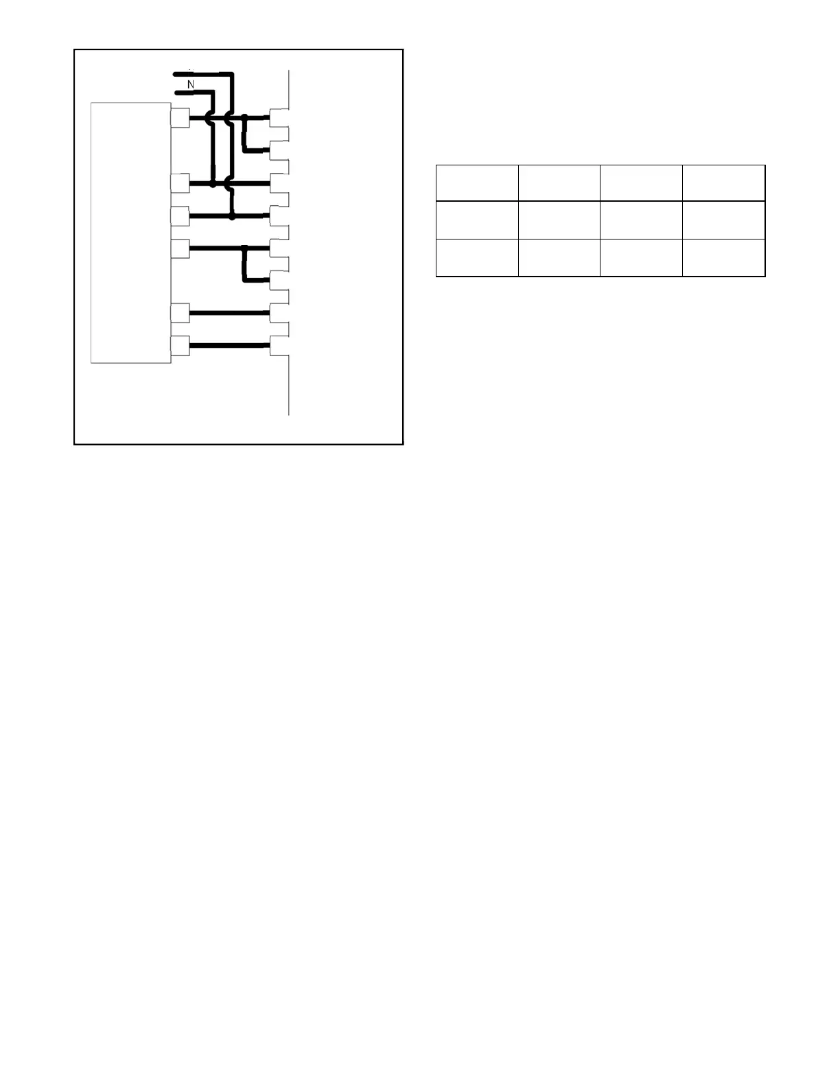
Figure 4-29 TP Sensor Wiring Diagram
The ECM monitors feedback from the electronic
throttle control (ETC) through leads TPS1 and TPS2.
The ECM controls the signal through leads ETN and
ETP to adjust the throttle position and maintain the
programmed engine speed.
Refer to Figure 4-29 and follow the steps in the
troubleshooting chart to check the throttle position
sensors TPS1 and TPS2. Verify that:
The TP sensor is working correctly and is not
damaged.
The sensor leads have continuity (no open
circuits).
The sensor leads are not shorted.
Closed Partially Open
Fully Open
TPS1 0V Between
0V–5V
5V
TPS2 5V Between
5V–0V
0V
P26-70, Sensor ground
ETC
P27-112, ETC–
1
2
104
40A
3
4
15
P26-15, TPS2
P26-34, TPS1
N1
34
To TMAP
sensor
N2
5
6
40B
40
112
N
105
113
ECM
P27-104, ETC–
P26-40, Sensor +5V
P27-113, ETC+
P27-105, ETC+
 Loading...