TP-6447 10/1212 Section 2 Installation
See Figure 2-2 or Figure 2-3 or the dimensional drawing
for the weight of the transfer switch. Use a spreader bar
to lift the transfer switch. Attach the bar only to the
enclosure’s mounting holes or lifting brackets; do not lift
the unit any other way. Close and latch the enclosure
door before moving the unit.
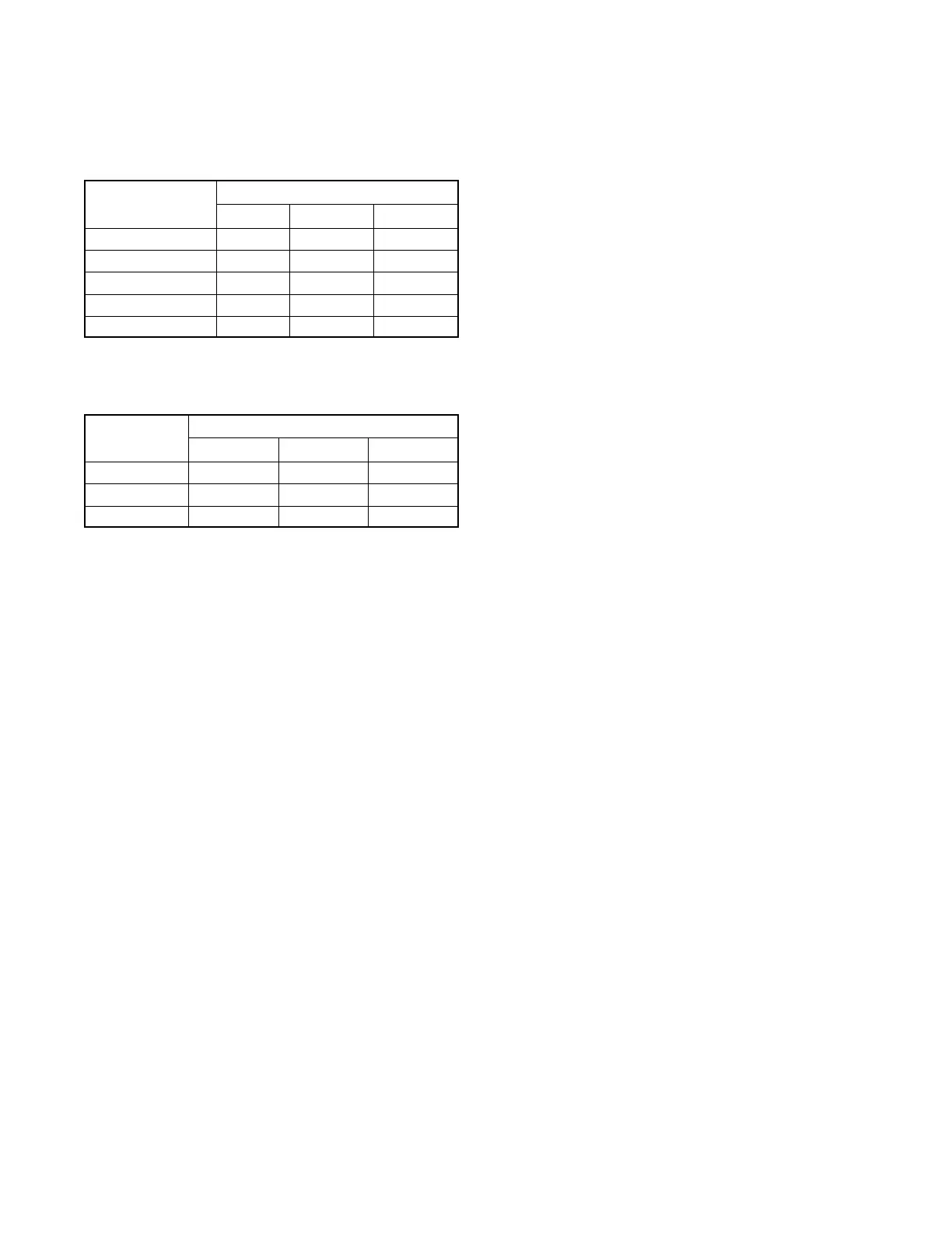
Amps
Weight kg (lb.)
2-Pole 3-Pole 4-Pole
40--225 28 (62) 30 (65) 31 (68)
260--400 52 (115) 56 (123) 59 (131)
600 179 (395) 183 (403) 186 ( 410)
800 N/A 226 (498) 236 (520)
1000 N/A 231 (509) 241 ( 531)
Figure 2-2 Approximate Transfer Switch Weights,
Standard-Transition Models, NEMA Type
1 and 3R Enclosures
Amps
Weight kg (lb.)
2-Pole 3-Pole 4-Pole
100--200 52 (115) 56 (123) 59 (131)
400 52 (115) 56 (123) 59 (131)
600 179 (395) 183 (403) 186 ( 410)
Figure 2-3 Approximate Transfer Switch Weights,
Programmed-Transition Models, NEMA
Type 1 and 3R Enclosures
2.2.4 Unpacking
Allow the equipment to warm to room temperature for at
least 24 hours before unpacking to prevent
condensation on the electrical apparatus. Use care
when unpacking to avoid damaging transfer switch
components. Remove dirt and packing material that
may have accumulated in the transfer switch or any of its
components.
Note: Do not use compressed air to clean the switch.
Cleaning with compressed air can cause debris to
lodge in the components and damage the switch.
2.3 Installation
NOTICE
Foreign material contamination. Cover the transfer switch
during installation to keep dirt, grit, metal drill chips, and other
debris out of the components. Cover the solenoid mechanism
during installation. After installation, use the manual
operating handle to cycle the contactor to verify that it
operates freely. Do not use a screwdriver to force the
contactor mechanism.
NOTICE
Hardware damage. The transfer switch may use both
American Standard and metric hardware. Use the correct
size tools to prevent rounding of the bolt heads and nuts.
Check the system voltage and frequency. Compare
the voltage and frequency shown on the transfer switch
nameplate to the source voltage and frequency. Do not
install the transfer switch if the system voltage and
frequency are different from the nominal normal (utility)
source voltage and frequency or the nominal emergency
source voltage and frequency shown on the generator
set nameplate.
Plan the installation. Use the dimensions given on the
enclosure dimension (ADV) drawings. Select a
mounting site that complies with local electrical code
restrictions for the enclosure type. Mount the transfer
switch as close to the load and power sources as
possible. Allow adequate space to fully open the
enclosure and to service the switch. Provide cable
bending space and clearance to live metal parts.
Outdoor installations. Transfer switches with
NEMA 3R, 4, or 4X enclosures can be installed
outdoors. In locations with very high ambient
temperatures, installation in a shaded area or a location
with the enclosure door facing away from direct sunlight
is recommended.
Prepare the foundation. Ensure that the supporting
foundation for the enclosure is level and straight. For
bottom cable entry, if used, install conduit stubs in the
 Loading...


