TP-6447 10/12 13Section 2 Installation
foundation. Refer to the enclosure dimension drawing
for the conduit stub locations. When pouring a concrete
floor, use interlocking conduit spacer caps or a wood or
metal template to maintain proper conduit alignment.
Install the ATS. For easy access during installation and
wiring, remove the front door of the enclosure. Open the
door and disconnect the cable plug that connects the
front door components to the internal components.
Disconnect the grounding wire between the door and the
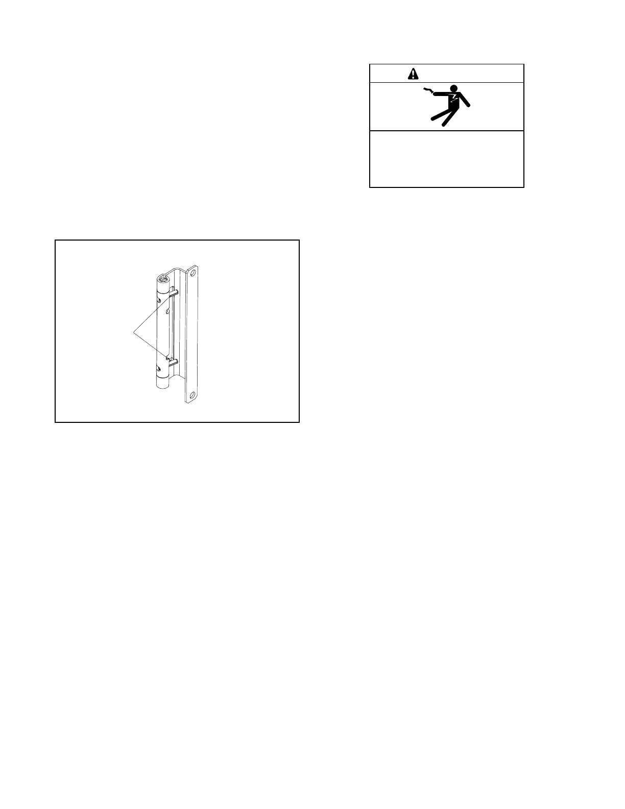
enclosure. For NEMA type 1 and 3R enclosures,
squeeze the release pins on each hinge together and
remove the door. See Figure 2-4. Set the door out of the
way to protect the controls. Cover the internal
components of the transfer switch mechanism to keep
debris out of the components.
1
6126
1. Hinge release pins
Figure 2-4 Hinge Release Pins
Vertically mount 40- through 400-amp transfer switches
to a wall or other rigid vertical supporting structure. Use
the template on the shipping carton to locate the
mounting holes in the wall. Level the template before
marking and drilling the holes. Clearance holes through
the back of each enclosure are provided for mounting.
Use shims to plumb the enclosure. Verify that the door
hinges are vertical to avoid distortion of the enclosure or
door. Vacuum any debris out of the enclosure.
Bolt 600-amp automatic transfer switches directly to
floor mounting pads. Shim the enclosure so that the
enclosure is plumb.
2.4 Manual Operation Check
Hazardous voltage.
Will cause severe injury or death.
Disconnect all power sources before
opening the enclosure.
DANGER
NOTICE
Improper operator handle usage. Use the manual operator
handle on the transfer switch for maintenance purposes only.
Return the transfer switch to the normal position. Remove the
manual operator handle, if used, and store it in the place
provided on the transfer switch when service is completed.
A manual operation handle is provided with the transfer
switch for maintenance purposes only. Use the manual
operation handle to check the manual operation before
energizing the transfer switch. Use the following manual
operation procedures to verify that the contactor
operates smoothly without binding.
Note: A contactor in normal and serviceable condition
operates smoothly without binding. Do not place
the transfer switch into service if the contactor
does not operate smoothly; contact an authorized
distributor/dealer to service the contactor.
2.4.1 Manual Operation Procedure,
Standard-Transition Switches
Note: Never use the maintenance handle to transfer the
load with the power connected. Disconnect both
power sources before manually operating the
switch.
1. Remove the maintenance handle from its storage
location inside the enclosure. See Figure 2-5
through Figure 2-7.
2. Attach the maintenance handle:
a. 40--600 Amp switches: Insert the maintenance
handle into the hole in the shaft on the left side
of the operator as shown in Figure 2-5 or
Figure 2-6.
b. 800--1000 Amp switches: Slide the
maintenance handle over the square shaft on
the left side of the operator as shown in
Figure 2-7.
 Loading...


