6
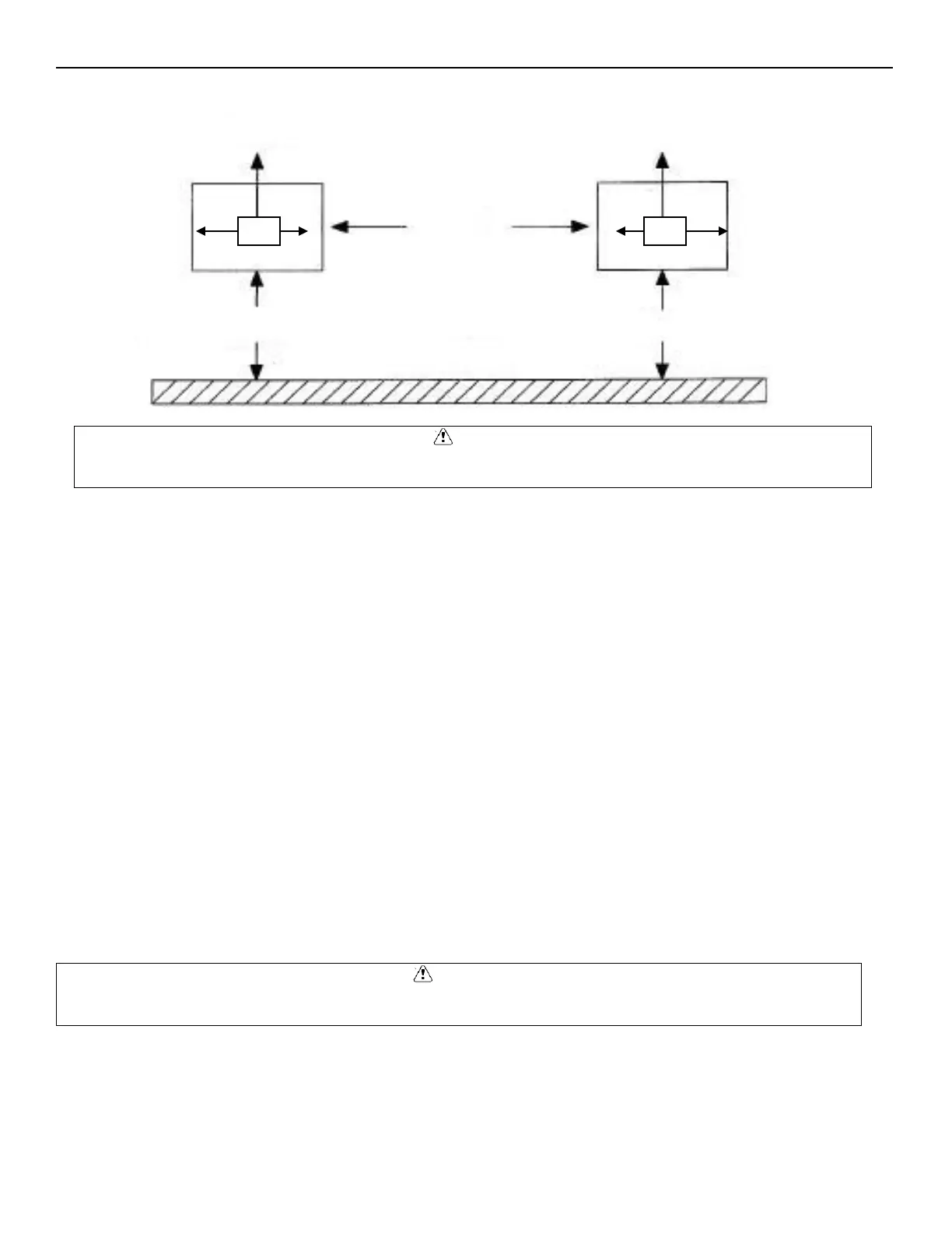
Example of Multiple Units with Horizontal Airflow
Evaporator Units
• Do not place the evaporator above or close to door openings. This will help prevent potential icing problems.
• Allow a minimum clearance equal to or greater than the coil height on all sides of the coil for proper air flow and
service access.
• Use the evaporator coil for a template to locate and drill the mounting holes (1/2” diameter).
• Place a 1” and a 1-5/8” washer on each nylon bolt and insert through the drilled mounting holes in the ceiling from
the exterior of the walk-in ceiling panel.
NOTE: Nylon bolts are supplied to prevent thermal transfer between the exterior of the walk-in and the interior of the walk-
in. Do not use metal bolts.
• Lift the evaporator coil until the nylon bolts extend through the mounting brackets.
• Install washers and secure with nuts. Tighten until the coil is firm against the ceiling. The evaporator coil must be
level.
• Additional information is available in the installation manual supplied with the evaporator.
CAUTION
Failure to observe clearance and air flow requirements will result in poor system performance and premature
Failure to observe clearance and air flow requirements will result in poor system performance and premature equipment
BUILDING WALL
(VIEWED FROM ABOVE)
FLOW
FLOW
DISTANCE
24”
MINIMUM DISTANCE 24”
MINIMUM DISTANCE 24”