12. OPERATION
12.16.2 INSPECTION AND ADJUSTMENT
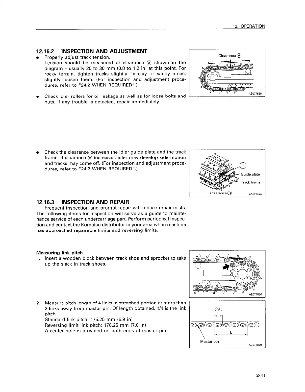
l Properly adjust track tension.
Tension should be measured at clearance @ shown in the
diagram - usually 20 to 30 mm (0.8 to 1.2 in) at this point. For
rocky terrain, tighten tracks slightly. In clay or sandy areas,
slightly loosen them. (For inspection and adjustment proce-
dures, refer to “24.2 WHEN REQUIRED”.)
l Check idler rollers for oil leakage as well as for loose bolts and
nuts. If any trouble is detected, repair immediately.
Clearance @
l Check the clearance between the idler guide plate and the track
frame. If clearance @ increases, idler may develop side motion
and tracks may come off. (For inspection and adjustment proce-
dures, refer to “24.2 WHEN REQUIRED”.)
12.16.3 INSPECTION AND REPAIR
Frequent inspection and prompt repair will reduce repair costs.
The following items for inspection will serve as a guide to mainte-
nance service of each undercarriage part. Perform periodical inspec-
tion and contact the Komatsu distributor in your area when machine
has approached repairable limits and reversing limits.
Measuring link pitch
1. Insert a wooden block between track shoe and sprocket to take
up the slack in track shoes.
2. Measure pitch length of 4 links in stretched portion at more than
2 links away from master pin. Of length obtained, l/4 is the link
pitch.
Standard link pitch: 175.25 mm (6.9 in)
Reversing limit link pitch: 178.25 mm (7.0 in)
A center hole is provided on both ends of master pin.
\ c
L
Master pin
AE077860
2-41
 Loading...