2-22
PC210/240-ENG
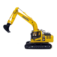
3. LEFT WORK EQUIPMENT CONTROL LEVER
(with auto-deceleration device)
WARNING
If any lever is operated when in the deceleration range, the en-
gine speed will suddenly increase, so be careful when operating
the levers.
This lever is used to operate the arm and upper structure.
Arm operation Swing operation
A Arm OUT C Swing to right
B Arm IN D Swing to left
N (Neutral)
When the lever in this position, the upper structure and the arm will
be retained in the position in which they stop.
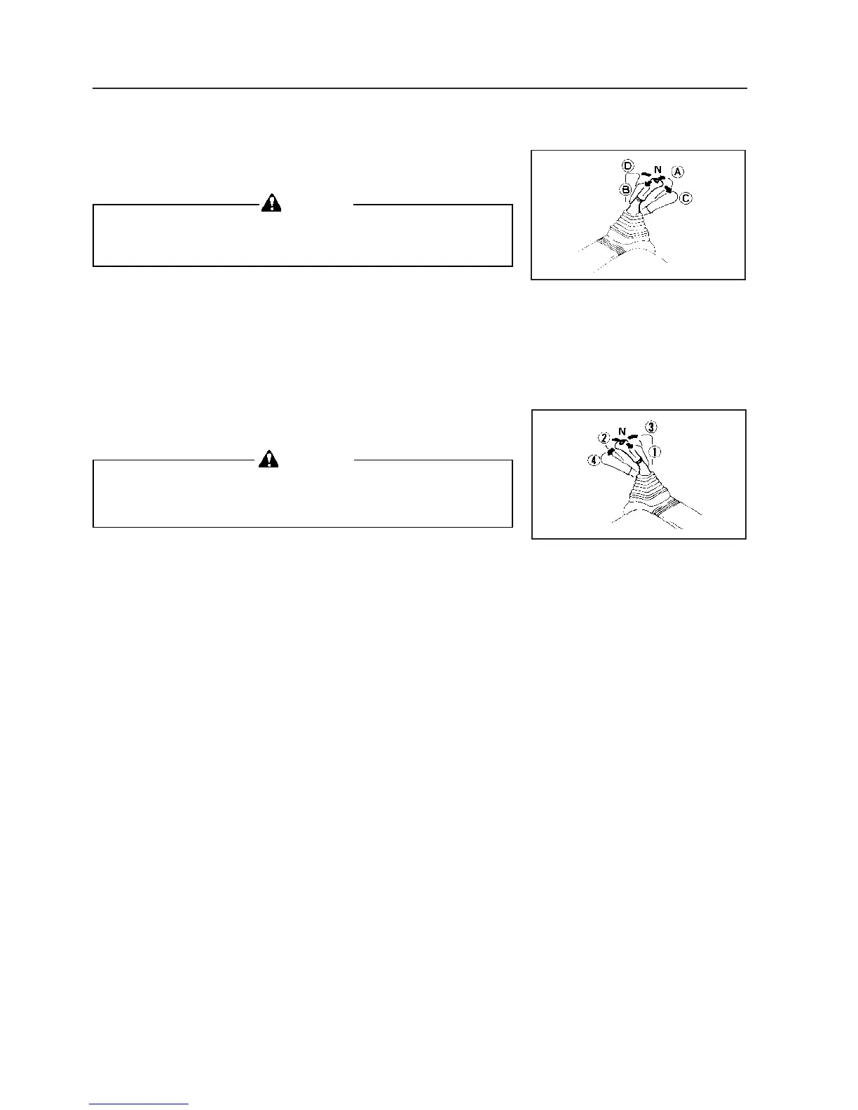
4. RIGHT WORK EQUIPMENT CONTROL LEVER
(with auto-deceleration device)
WARNING
If an lever is operated when in the deceleration range, the engine
speed will suddenly increase, so be careful when operating the
levers.
This lever is used to operate the boom and bucket.
Boom operation Bucket operation
y RAISE c DUMP
x LOWER v CURL
N (Neutral)
When the lever in this position, the boom and the bucket will be
retained in the position in which they stop.
For levers b, c and d, the engine speed changes as follows be-
cause of the auto-deceleration mechanism.
• When the travel lever and work equipment control levers are at
neutral, even if the fuel control dial is above the mid-range position,
the engine speed will drop to a mid-range speed. If any of the le-
vers are operated, the engine speed will rise to the speed set by
the fuel control dial.
• If all control levers are set to neutral, the engine speed will drop by
approx. 100 rpm, and after approx. 4 seconds, the engine speed
will drop to the deceleration speed (approx. 1400 rpm).
11. EXPLANATION OF COMPONENTS
 Loading...