SECTION 2 - SET-UP & OPERATIONS
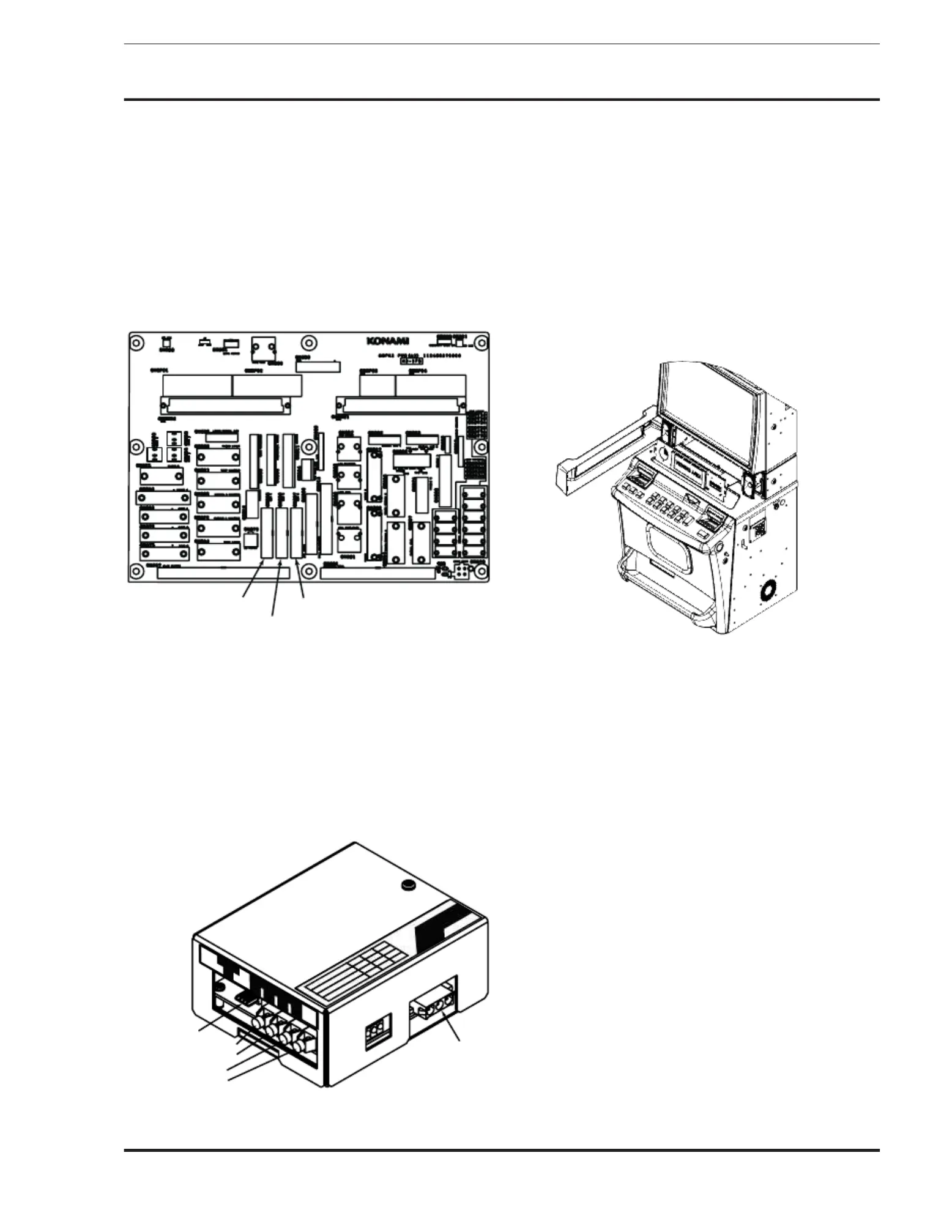
The Slot Accounting System (SAS) communication with the
video gaming machine takes place via interface connectors located on
the Backplane board in the Logic Unit box and setting
Maintenance System (KMS).
Under typical conditions, CNB35/Port 1 on the backplane, is for
Unit, used for ber optic interface. CNB36
and CNB37 are used for serial communications with conventional
The Backplane is shown in greater detail in
When ber optic communication lines are used, they are rst
routed to the SAS Unit mounted in the machine. The SAS Unit is
equipped with two input and two output ber optic receptacles. The
SAS unit is also equipped with a serial input/output connector and
attached wiring, the output of which is connected to
The SAS components are mounted on a removable bracket
installed on top of the box. Use the following illustration to remove
Open the Main Door and turn power off. Open the system
enclosure by un-locking the door. Loosen, but do not remove, two
(2) 6-32x1/4 screws holding the bracket in place. Lift the bracket and
pull it forward to remove.
Place the bracket keyhole slots over the 6-32x1
the bracket down and tighten the
This section, Installation, describes the procedure for
the cabinet and the initial settings of
Opening and Closing the Doors
This section describes how to check the version of the cabinet
and the optional parts provided. This information will help in perfor
the work from initialization to operation of this
Check the serial number. The following explains how to
the serial number using the Serial Number Plate or referring to the
stamped or engraved serial
 Loading...