Do you have a question about the Konami KGP 3.5 PDM2 and is the answer not in the manual?
Information on contacting Konami Gaming for service and support.
Outlines the warranty terms and the process for returning defective parts.
Provides instructions for unpacking and inspecting the machine for damage upon arrival.
Guidance on replacing lock cylinders and hardware for machine doors.
Explains the function and configuration of the bill acceptor module.
Details pre-operation checks, cabinet inspection, and environment checks.
Instructions for removing and installing the power supply unit.
Details the removal and installation of the Main Processing Unit (MPU).
Provides instructions for removing and installing the logic unit.
Covers the removal and installation of the backplane board.
Instructions for removing and installing the bill validator unit.
Instructions for removing and installing the power distribution assembly.
Details the removal and installation of the LCD unit.
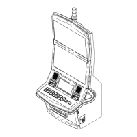
Part breakdown and diagram for the main cabinet assembly, part 1 of 6.
Part breakdown and diagram for the main cabinet assembly, part 2 of 6.
Part breakdown and diagram for the main cabinet assembly, part 3 of 6.
Part breakdown and diagram for the main cabinet assembly, part 4 of 6.
Part breakdown and diagram for the main cabinet assembly, part 5 of 6.
Part breakdown and diagram for the main cabinet assembly, part 6 of 6.
Part breakdown and diagram for the main deck assembly.
Part breakdown and diagram for the main deck and frame assembly.
Part breakdown and diagram for the sub door assembly.
Part breakdown and diagram for the power supply assembly.
Part breakdown and diagram for the LCD assembly with touch screen.
Part breakdown and diagram for the LCD assembly without touch screen.
Part breakdown and diagram for the power control panel assembly.
Part breakdown and diagram for the international power control panel assembly.
Part breakdown and diagram for the CPU housing assembly.
Part breakdown and diagram for the KP 3.5 main board assembly.
Part breakdown and diagram for the right elbow assembly.
Part breakdown and diagram for the JCM IVIZION bill validator assembly.
Lists parts for the main machine assembly specific to VLT Quebec build.
| Brand | Konami |
|---|---|
| Model | KGP 3.5 PDM2 |
| Category | Arcade Game Machines |
| Language | English |