Do you have a question about the Konami KX43 and is the answer not in the manual?
Provides contact information and support services for Konami gaming machines.
Details the warranty policy and the procedure for returning defective parts.
Explains shipping responsibilities for warranty and expedited items.
Compliance with FCC rules for radio frequency interference.
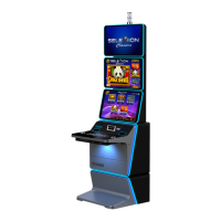
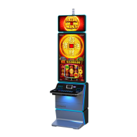
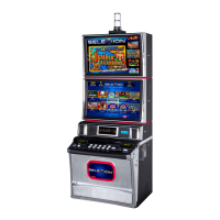
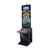
Lists machine features, including LCD, topper, and available bill acceptors.
Definitions of key terms used throughout the manual.
Explains important notices, cautions, and warnings for safe operation.
Cabinet dimensions, weight, and operating environment requirements.
Procedures for safely unpacking and inspecting the machine for damage.
Instructions for installing the signal tower candle.
Details connecting the Drop Box Switch and Slot Accounting System.
Instructions for removing and installing the player tracking panel.
Routing and connection of fiber optic communication lines.
Procedures for opening and closing the main and logic unit doors.
Steps for opening and closing cashbox, sub, and bill validator doors.
Steps to safely remove the machine's display unit.
Procedures for installing the machine's display unit.
Instructions for removing and installing the optional topper unit.
Guidance on replacing or changing the machine's locks.
Steps for replacing standard lock hardware and logic unit door locks.
Steps for replacing the lock on the main deck door.
Procedure for replacing the lock on the bill validator door.
Explanation of how the bill acceptor handles bills and credits.
Covers collecting bills and operating the cashbox door lock.
Details player interface, spin buttons, and bill entry.
Describes the 43" LCD, service, cashout, line, and bet buttons.
Covers initial startup procedures, cabinet inspection, and power connection checks.
Introduces maintenance procedures and lists necessary tools.
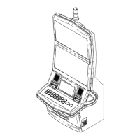
Illustrates and identifies major machine components.
Lists standard hardware components used in the machine.
Details how to connect door switch wires.
Procedures for removing and installing the sub door switch.
Procedures for removing and installing the main deck door switch.
Steps for removing and installing the machine's key switch.
Procedures for removing and installing the bill validator switch assembly.
Steps for removing and installing the cashbox door switch.
Procedures for removing and installing the logic unit switch.
Instructions for removing and installing the power supply unit.
Procedures for removing and installing the bill validator.
Steps for removing and installing the logic unit.
Procedures for installing the main processing unit board.
Instructions for removing and installing the backplane board.
Procedures for removing and installing the printer assembly.
Steps for removing and installing the speaker units.
Procedures for removing and installing the power distribution assembly.
Instructions for removing and installing the meter assembly.
Directs users to a separate manual for troubleshooting procedures.
Refers users to a separate manual for preventive maintenance tasks.
Introduces the section containing wiring diagrams for the KX43.
Lists various electrical components used in the KX43 cabinet.
Lists the Printed Circuit Boards (PCBs) used in the KX43.
Lists the types and ratings of fuses used in the machine.
| Brand | Konami |
|---|---|
| Model | KX43 |
| Category | Arcade Game Machines |
| Language | English |