SECTION 2 - SET-UP
-2-4
2-4 © 2018 Konami Gaming Inc P/N 810440
KX43
(Original Instructions)
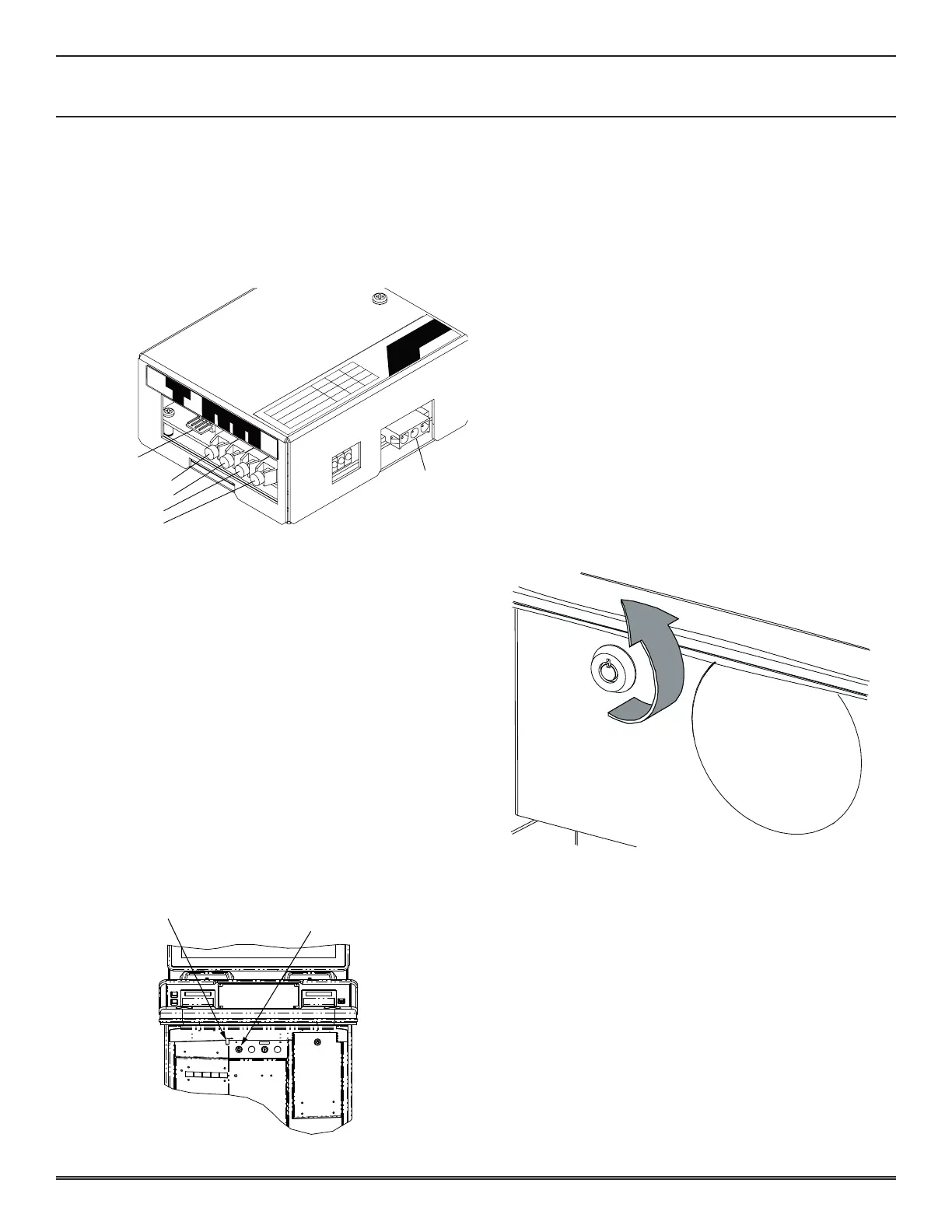
Fiber optiC interFaCe
When ber optic communication lines are used, they are rst
routed to the SAS Unit mounted in the machine� The SAS
Unit is equipped with two input and two output ber optic
receptacles� The SAS unit is also equipped with a serial input/
output connector and attached wiring, the output of which is
connected to the CNB35 port on the Backplane board�
SERIAL
I/O
AC115V IN
Green : Communication
Blink
Lit Off
Normal
Error Idling
Normal
Error
Idling
Normal
Error Idling
Red : Opto IN2 Monitor
Yellow : Terminal Serial Data
SERIAL
I/O
OUT1 OUT2 IN1 IN2
SERIAL I/O
FIBER OPTIC OUT 1
FIBER OPTIC OUT 2
FIBER OPTIC IN 2
AC 115V IN
CABINET INSTALLATION
This section describes the procedure for installing the cabinet
and setup of the initial settings of the equipment�
• Opening and Closing Doors
• Changing Locks
OPENING AND CLOSING THE DOORS
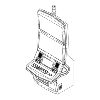
Main deCk door
1� To open the Main Deck Door, insert Main Deck Door Key
into Key Cylinder underneath the Main Deck�
2� Turn key 90° clockwise while simultaneously applying
pressure on the surface of Main Deck Door�
3� Pull pin button with key turned�
4� Open Main Deck Door�
LOCK
5� Close Main Deck Door with the key turned clockwise�
6� Turn key 90° counter-clockwise and remove from cylinder�
logiC unit door
1� To open the Logic Unit Door, insert the Logic Unit Door
key into the cylinder on the front of the Logic Unit�
2� Turn the key 90° counter-clockwise�
3� Open the Logic Unit Door by pulling the Logic Door toward
you and up to clear the mounting tabs�
4� To close the Logic Unit Door, insert the Logic Unit Door
tabs into the slots and pivot into the locking position�
5� Turn the Logic Door key 90° clockwise�
6� Remove the Logic Unit Door key from the cylinder�