SECTION 2 - SET-UP
-2-2
2-2 © 2018 Konami Gaming Inc P/N 810440
KX43
(Original Instructions)
• Power supply output voltage: +12 VDC, +24 VDC�
• Current draw at rest: 1�6 A (192 W)�
• Current draw at rest, with topper: 1�9 A (228 W)�
• Current draw during game play: 1�7 A (204 W)�
• Current draw during game play, with topper: 2�0 A
(240 W)�
• Maximum operating ambient temperature: 104° F
(40° C)�
• Minimum operating ambient temperature: 32° F (0° C)�
• Maximum surface ambient temperature: 105° F (41�5° C)�
• Minimum surface ambient temperature: 32° F (0° C)�
• Maximum relative humidity: 95% (non-condensing)�
UNPACKING AND INSPECTING
Unpack and inspect the machine before you turn on the
power� If the machine has been damaged during shipping,
contact your Konami Distributor, or Konami Customer Service
Representative, depending on warranty and sales contract
terms�
For Return Merchandise Authorization (RMA) information,
see Section 1 of this manual�
Carefully unpack and remove all loose parts and shipping
materials� Then, do the following:
• Inspect components for damage�
• Verify the power cord is properly routed from the cabinet�
• Verify all wire connectors are rmly seated.
• Check all display areas for signs of broken glass or bulbs�
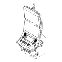
INSTALLING THE CANDLE
1� Remove the candle cover screws (4)�
2� Remove the ground nut�
3� Mount the Candle with two UNC 8-32 screws�
4� Connect the Candle to Wiring Harness in the machine�
5� If equipped, secure Frame Ground (FG) wire of the Candle
with the M3 nut�
6� Install candle cover screw (4) (M3)�
7� Turn power on and verify that the Candle illuminates�
Candle pin aSSignMent
CANDLE PIN ASSIGNMENT
PIN
NUMBER
WIRE
COLOR
SIGNAL
ASSIGNED
LIGHT
LOCATION
1 BROWN TL0 BOTTOM
2 BLUE TL1
TOP
3 VIOLET TL2
CANDLE PIN ASSIGNMENT
PIN
NUMBER
WIRE
COLOR
SIGNAL
ASSIGNED
LIGHT
LOCATION
4 GREY TL3 RESERVED
5 N� C� N� C�
6 YELLOW +24 V
DROP BOX SWITCH CONNECTION
NOTE: The Drop Box Switch wiring is typically used
ONLY when the machine is not connected to a slot
1� Open the Main Deck Door�
2� Locate the connector labeled DROP (on the main cabinet
harness)�
3� Connect the optional Drop Switch Harness (P/N 110324)�
4� Connect the three spade connectors to the Drop Switch�
CheCk drop box SWitCh operationS
If any of the following problems arise after turning the power
on, check that the Drop Box Switch is installed properly�
• The 031 DROP DOOR ACCESSED error message is
not displayed even after the power is turned on again
with the drop-door closed�
• The 041 DROP DOOR PORT error message is
displayed�
• No error messages appear when the Sub Panel is
opened and closed�
A Drop Door open accessed error can be detected even with
the power turned off� Reset the error and turn the power on
to check that the switch is installed correctly�
DROP BOX SWITCH PIN ASSIGNMENT
PIN # PIN ASSIGNMENT DESCRIPTION
1 GND GND (COM)
2 SW_DROP
SECURITY
(SW DROP BOX DOOR
(N�O�))
3 BSW_DROP
SECURITY
(SW DROP BOX DOOR
(N�C�))
4 N� C� -
SLOT ACCOUNTING SYSTEM CONNECTIONS
overvieW
The Slot Accounting System (SAS) communication with the
video gaming machine takes place via interface connectors
located on the Backplane board in the Logic Unit box and
through settings in the Konami Maintenance System (KMS)�