SECTION 2 - SET-UP
1-2-2
2-2
© 2018 Konami Gaming Inc. P/N 810237
CONCERTO UPRIGHT
(Original Instructions)
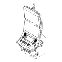
INSTALLING THE CANDLE
Open main deck door and remove display door. Pass candle
connector through the hole in the top of the machine. Mount
the candle with two UNC 8-32 nuts. If equipped, secure frame
ground (FG) wire of candle with one of the 8-32 nuts. Install
and lock display door, and close and lock main deck door.
Turn power on and verify that candle illuminates.
candle Pin assignMent
CANDLE PIN ASSIGNMENT
PIN NUMBER WIRE COLOR SIGNAL
ASSIGNED
LIGHT LOCATION
1 BROWN TL0 BOTTOM
2 BLUE TL1
TOP
3 VIOLET TL2
4 GREY TL3 RESERVED
5 N. C. N. C.
6 YELLOW +24 V
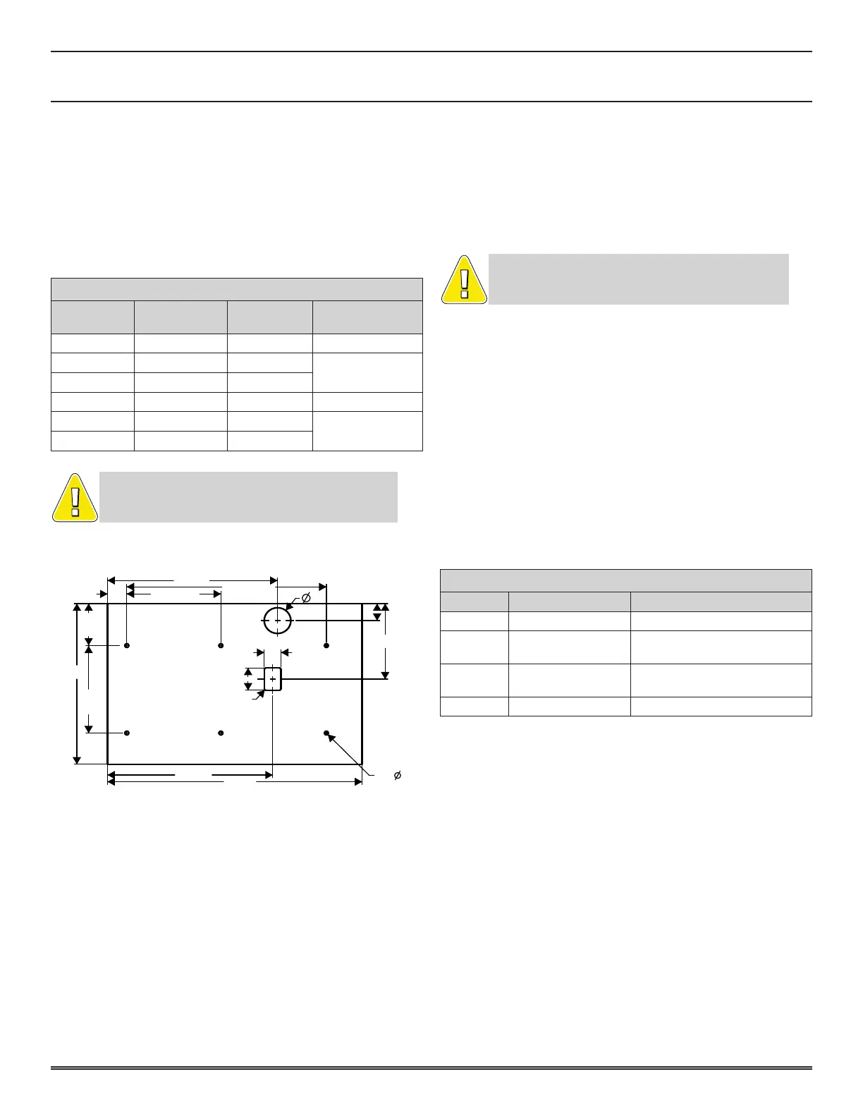
STAND DRILL GUIDE
15.949
2X 18.728
2X 8.8282X 1.806
2.50
1.648
7.334
1.580
2.160
3X
4.074
15.60
3X
8.500
4X R.12
15.494
23.88
6X .375
NOTE: To ensure proper spacing between machines, the
minimum allowable width of the stand a Konami machine
can be mounted on is 28”.
DROP BOX SWITCH
1. Open the Main Door.
2. Locate the connector labeled DROP (on the main cabinet
harness).
3. Connect the optional Drop Switch Harness (P/N 110324).
4. Connect the three spade connectors to the Drop Switch.
NOTE: The Drop Box Switch wiring is typically used
ONLY when the machine is not connected to a slot
cHeck droP sWitcH oPerations
If any of the following problems arise after turning the power
on, check that the Drop Box Switch is installed properly.
• The 031 DROP DOOR ACCESSED error message is not
displayed even after the power is turned on again with
the drop-door closed.
• The 041 DROP DOOR PORT error message is displayed.
• No error messages appear when the Sub-Door is opened
and closed.
A Drop Door open accessed error can be detected even with
the power turned off. Reset the error and turn the power on
to check that the switch is installed correctly.
DROP BOX SWITCH PIN ASSIGNMENT
PIN # PIN ASSIGNMENT DESCRIPTION
1 GND GND (COM)
2 SW_DROP
SECURITY
(SW DROP BOX DOOR (N.O.))
3 BSW_DROP
SECURITY
(SW DROP BOX DOOR (N.C.))
4 N. C. -
 Loading...