14
Issue 1.0 16/12/99
3 ASSEMBLY INSTRUCTIONS
3.1 General Assembly : Rotary Drive SRD12
The motor and gearbox are provided as a complete assembly and are not recom-
mended for piece part replacement. Refer to Drawing No. SRD12 and attach the PCB
by fastening the 3 screws Part No. 200000. Place the magnet carrier Part No. E02451
onto the shaft, metallic ends of the magnets towards the PCB, and push fit close to
the Hall Effect devices but without fouling. Apply Loctite 4105 to the inside surface of
the solenoid switch bracket and attach the bracket to the solenoid as shown. Attach
the NMEA control cable, motor, solenoid, solenoid switch connections and power ter-
minals, offer up the case top and secure the case bolts.
3.2 General Assembly : SFC12 Control Unit
Refer to Drawing No. SFC12 and fit the screened cable (E02922) through the retain-
ing nut E02904:BK, gasket E03099, case bottom (E02902:BK) and grommet
(E03701) and terminate it on the PCB. Fit the PCB into the bottom case carefully
locating it onto the rubber grommet. Fit Gasket (E03702) into the recess in the bot-
tom case and fit the top case (E03676) onto the bottom case ensuring that the case
seal remains correctly located. Fit the 4 off Pan Poz Drive Screws into the 4 recessed
holes in the case bottom and screw up firmly to retain the case top.
3.3 General Assembly : Junction Box
Refer to Drawing No. SJB12. The drawing is self explanatory and needs no further
explanation.
3.4 General Assembly : Heading Sender
Refer to Drawing No. SHS12 and fit the screened cable (E02922) through the case
bottom (E02781:BK) and grommet (E03701) and terminate it on the PCB. Fit the PCB
complete with compass into the bottom case carefully locating it onto the rubber grom-
met. Fit gasket E02783 in the recess in the top case and fit the top case onto the bot-
tom case using 2 off 200235 screw No. 4 x 1” and 1 off 200137 screw No.4 x 3/4” each
fitted with a washer 200184. NB. The short screw is used in the front of the case with
the longer screws to the flat edge at the rear.
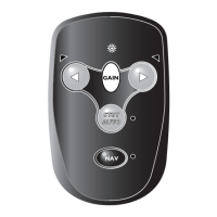
3.5 General Assembly : Remote Control
Refer to Drawing No. E03709 and fit the cable assembly (E03281) through the case
rear (E02737:BK) and grommet (E03701) and terminate it on the PCB. Locate the 5
screw boss seals (E02555) and fit the PCB into the case rear carefully locating it onto
the screw boss seals and secure with the 2 screws (200139) complete with washers
(200081). Locate the case seal (E02541) into the groove in the case rear and fit the
case top assembly to the case rear and secure using the 5 screws (200139).




 To Next Page