25
Issue 1.0 16/12/99
5.4 SHC14 PCB Assembly
Introduction
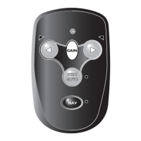
The Remote Control Unit provides the same facilities as the fixed control unit with
additional options of: manual control of sea state, alarm set and response speed,
dodge facility, compass read-out and rudder position indication. The circuit diagram
for the PCB is given in Drawing No. E02552.
Supply and Regulation. The SHC14 is designed to work from a 12 V source.
Protection against incorrect polarity connection is provided by D1 with protection
against over-voltage spikes provided by ZD1. REG1 and associated smoothing
capacitors provide a 5V regulated supply from which the internal circuitry is powered.
Diodes D6 and D7 and TR4 provide isolation of the supply from the printed circuit
board until the 0V connection is made back to the supply. This prevents partial con-
duction via the positive line and bus line through the bus drive circuitry if the 0V line
is not connected and hence prevents lock up of the main pilot circuit.
Interface. Bus interface is provided by IC7b and associated components.
LCD Drivers. LCD driving is provided by IC6 to which data is sent via an 8 bit paral-
lel bus from the microprocessor. TR3 and associated components including D3 and
D4 provide a negative voltage drive for the LCD. Resistor train R20 to R24 provides
the appropriate voltage levels for LCD operation. Oscillation for the negative voltage
generator is provided by circuitry associated with IC8a.
Microprocessor. The microprocessor reads the key matrix S1 to S9 directly, gives
the relevant commands to the LCD and the Bus and provides drive signals to the
back-light via TR1 and to the buzzer via TR2.
EMC. A variety of measures are included in the circuit to limit the susceptibility of the
circuit to interference and to provide reduction of emissions. Extensive de-coupling of
the microprocessor I / O lines is carried out using 100pF capacitors.



 To Next Page