50
2.2 Component names and functions
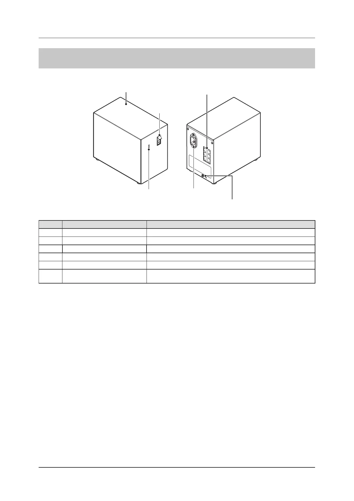
2.2.8 Power Supply Unit
The component names and functions of the Power Supply Unit are as follows.
(5) Inlet
(1) Base cover
(4) LED
(3) LAN port
(2) Power switch
(6)
Location for connecting
the grounding cable
Number Name Functions
(1) Base cover Protects the internal parts.
(2) Power switch Turns the Power Supply Unit on/o.
(3) LAN port Connects to the Ethernet cable.
(4) LED Indicates the status of the Power Supply Unit.
(5) Inlet Connects to the power cable of Power Supply Unit.
(6)
Location for connecting the grounding
cable
Used to connect the grounding cable.Not usually used.
 Loading...